Information governor
BOSCH
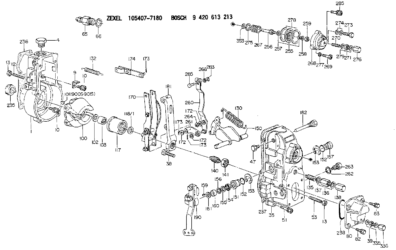
9 420 613 213
9420613213
ZEXEL
105407-7180
1054077180
Rating:
Scheme ###:
| 1. | [1] | 154000-5720 | GOVERNOR HOUSING |
| 4. | [1] | 154007-1600 | CAPSULE |
| 9. | [1] | 154350-6000 | PLATE |
| 10. | [8] | 020106-2040 | BLEEDER SCREW M6P1L20 |
| 10. | [8] | 020106-2040 | BLEEDER SCREW M6P1L20 |
| 12. | [1] | 154010-1100 | FLAT-HEAD SCREW |
| 13. | [2] | 154011-0100 | HEXAGON NUT |
| 13. | [2] | 154011-0100 | HEXAGON NUT |
| 35. | [1] | 154022-6020 | GOVERNOR COVER |
| 38. | [1] | 154031-5000 | FLAT-HEAD SCREW |
| 39. | [1] | 139208-0400 | UNION NUT |
| 47. | [1] | 154036-0300 | CAPSULE |
| 51. | [6] | 020106-5040 | BLEEDER SCREW |
| 53. | [1] | 154010-0200 | FLAT-HEAD SCREW |
| 65. | [1] | 153021-2220 | STOPPING DEVICE |
| 66. | [1] | 026524-3040 | GASKET |
| 80. | [1] | 154063-8400 | COVER |
| 82. | [2] | 029020-6210 | BLEEDER SCREW |
| 83. | [2] | 020006-1640 | BLEEDER SCREW M6P1L16 4T |
| 100. | [1] | 154101-0020 | FLYWEIGHT ASSEMBLY |
| 101. | [1] | 025803-1310 | WOODRUFF KEY |
| 102. | [1] | 029321-2020 | LOCKING WASHER |
| 103. | [1] | 029231-2030 | UNION NUT |
| 117. | [1] | 154123-2320 | SLIDING PIECE |
| 118/1. | [0] | 029311-0010 | SHIM D14&10.1T0.2 |
| 118/1. | [0] | 029311-0180 | SHIM D14&10.1T0.3 |
| 118/1. | [0] | 029311-0190 | SHIM D14&10.1T0.40 |
| 118/1. | [0] | 029311-0210 | SHIM D14&10.1T1 |
| 118/1. | [0] | 139410-0000 | SHIM D14.0&10.1T0.5 |
| 118/1. | [0] | 139410-0100 | SHIM D14.0&10.1T1.5 |
| 118/1. | [0] | 139410-3000 | SHIM D14&10.1T2.0 |
| 118/1. | [0] | 139410-3100 | SHIM D14&10.1T3.0 |
| 118/1. | [0] | 139410-3200 | SHIM D14&10.1T4.0 |
| 130. | [1] | 154150-6400 | GOVERNOR SPRING |
| 132. | [1] | 154154-0701 | COILED SPRING |
| 135. | [1] | 154158-1720 | HEADLESS SCREW |
| 136. | [1] | 029201-2290 | UNION NUT |
| 137. | [2] | 026512-1540 | GASKET D15.4&12.2T1.50 |
| 138. | [1] | 154159-1200 | CAP NUT |
| 140. | [1] | 154177-3520 | HEADLESS SCREW |
| 141. | [1] | 029201-6010 | UNION NUT |
| 150. | [1] | 154200-7020 | SWIVELLING LEVER |
| 151. | [1] | 154204-4300 | BUSHING |
| 152. | [2] | 139718-0200 | O-RING |
| 152. | [2] | 139718-0200 | O-RING |
| 153. | [2] | 016010-1640 | LOCKING WASHER |
| 153. | [2] | 016010-1640 | LOCKING WASHER |
| 154. | [1] | 139611-0300 | PACKING RING |
| 155. | [1] | 139411-0000 | SHIM |
| 156. | [0] | 029311-1070 | SHIM D16&11T0.5 |
| 157. | [1] | 154204-4400 | BUSHING |
| 159. | [1] | 025803-1310 | WOODRUFF KEY |
| 160. | [1] | 154206-2800 | BUSHING |
| 161. | [0] | 154206-0200 | PLAIN WASHER D19.5&11.2T1.0 |
| 170. | [1] | 154216-7220 | FORK LEVER |
| 172. | [3] | 029310-5170 | SHIM D8&5.3T0.5 |
| 172. | [3] | 029310-5170 | SHIM D8&5.3T0.5 |
| 172. | [3] | 029310-5170 | SHIM D8&5.3T0.5 |
| 173. | [3] | 025520-1210 | SPLIT PIN |
| 173. | [3] | 025520-1210 | SPLIT PIN |
| 173. | [3] | 025520-1210 | SPLIT PIN |
| 174. | [1] | 154230-2920 | STRAP |
| 181. | [1] | 154236-4100 | TENSIONING LEVER |
| 182. | [1] | 154237-1100 | BEARING PIN |
| 190. | [1] | 154395-4920 | CONTROL LEVER |
| 235. | [1] | 155412-5300 | IMPELLER WHEEL |
| 236. | [1] | 154371-5600 | GASKET |
| 237. | [1] | 154390-0300 | GASKET |
| 238. | [1] | 029635-2020 | O-RING |
| 255. | [1] | 154400-7420 | DIAPHRAGM |
| 256. | [1] | 154400-4800 | STOP PIN |
| 257. | [2] | 029330-8050 | GASKET |
| 258. | [1] | 139308-0700 | LOCKING WASHER |
| 259. | [1] | 013030-6040 | UNION NUT M6P1H3.6 |
| 260. | [1] | 154401-3620 | CONTROL LEVER |
| 261. | [1] | 154401-1320 | STRAP |
| 262. | [1] | 026510-1440 | GASKET D13.9&10.2T1 |
| 263. | [1] | 154401-2100 | BLEEDER SCREW |
| 264. | [1] | 016010-0540 | LOCKING WASHER |
| 265. | [1] | 154222-6200 | BEARING PIN |
| 266. | [1] | 029300-4010 | PLAIN WASHER |
| 267. | [1] | 154416-5500 | COILED SPRING |
| 268. | [1] | 154404-5600 | COVER |
| 269. | [2] | 020106-2540 | BLEEDER SCREW M6P1L25 |
| 270. | [1] | 154034-1900 | FLAT-HEAD SCREW |
| 271. | [1] | 013020-6040 | UNION NUT M6P1H5 |
| 273. | [1] | 029731-0180 | EYE BOLT |
| 274. | [2] | 029341-0110 | GASKET |
| 275. | [0] | 029312-0180 | SHIM D25.5&20T0.5 |
| 275B. | [0] | 029312-0210 | SHIM D25.5&20T0.2 |
| 276. | [1] | 154035-1600 | CAP NUT |
| 277. | [1] | 014110-6440 | LOCKING WASHER |
| 278. | [2] | 154413-2600 | GASKET |
| 279. | [2] | 026506-1040 | GASKET D9.9&6.2T1 |
| 283. | [1] | 016010-0440 | LOCKING WASHER |
| 285. | [1] | 029010-6310 | BLEEDER SCREW |
| 335. | [2] | 026508-1140 | GASKET D11.4&8.2T1 |
| 336. | [1] | 154035-2000 | CAP NUT |
| 353. | [2] | 029310-9080 | SHIM D16&9T1.7 |
| 900S. | [1] | 025803-1310 | WOODRUFF KEY |
| 901S. | [1] | 025803-1610 | WOODRUFF KEY |
Cross reference number
Zexel num
Bosch num
Firm num
Name
Information:
Crankshaft Grinding Specifications
The dimensions and finish for grinding crankshafts are as follows:Diameter (A) for connecting rod bearing journals is;.010 in. (0.25 mm) Undersize ... 2.7396 .0006 in.(69.586 0.015 mm).020 in. (0.51 mm) Undersize ... 2.7296 .0006 in.(69.332 0.015 mm).050 in. (1.27 mm) Undersize ... 2.6996 .0006 in.(68.570 0.015 mm)Surface finish must be 10 micro inches (0.25 micrometers) or less.Radius (B) must be .100 .010 in. (2.54 0.25 mm).Surface finish must be 63 micro inches (1.6 micrometers) or less.The radius must blend smoothly with the newly machined journals.
DIMENSIONS FOR GRINDING
A. Diameter of connecting rod bearing journals. B. Radius on connecting rod bearing journals. C. Width to grind journals for the connecting rods. D. Diameter of main bearing journals. E. Radius on main bearing journals. F. Width to grind journals for the main bearings.Width (C) is 2.314 .003 in. (58.77 0.08 mm)Diameter (D) for main bearing journals is:.010 in. (0.25 mm) Undersize ... 3.4895 .0006 in.(88.633 0.015 mm).020 in. (0.51 mm) Undersize ... 3.4795 .0006 in.(88.379 0.015 mm).050 in. (1.27 mm) Undersize ... 3.4495 .0006 in.(87.617 0.015 mm)Surface finish must be 10 micro inches (0.25 micrometers) or less.Radius (E) must be .095 .010 in. (2.41 0.25 mm)Surface finish must be 63 micro inches (1.6 micrometers) or less.The radius must blend smoothly with the newly machined journals.Width (F) is 1.258 .002 in. (31.95 0.05 mm) for number 4 main bearing journal. Surface finish on the thrust faces of the number 4 main must be 18 micro inches (0.45 micrometers) or less.Width (F) is 1.268 + .020 - .010 in. (32.21 + 0.51 - 0.25 mm) for number 2, 3, and 5 main bearing journals.There is no width (F) for number 1 main bearing journal.When grinding a crankshaft, no material can be removed from the crankshaft webs or counterweights.Crankshaft Gear Removal
Remove the gear using an 8B7548 Push Puller, 8B7551 Bearing Pulling Attachment, 8B75621 Step Plate, and 8H684 Ratchet Box Wrench.
PULLING CRANKSHAFT GEARThe 1P820 Hydraulic Puller Group can also be used to pull gear from crankshaft. Tools required are 1P820 Hydraulic Puller Group, 8B7551 Bearing Pulling Attachment, 8B7549 Puller legs (two), 8B7561 Step Plate, 3H465 Plate (four), 1B4207 Nut (two), and 5P3100 Pump Group.
USING HYDRAULIC PULLERCrankshaft Gear Installation
1. Install the key in keyway of crankshaft. Remove all burrs from key and keyway inside of crankshaft gear.2. Heat gear to 500°F (260°C) maximum.3. Install gear on crankshaft with timing mark on gear facing front of crankshaft.Crankshaft Front Oil Seal Removal
Remove the crankshaft front pulley. Use the 1P3075 Puller Group to remove the crankshaft front oil seal.
REMOVING FRONT OIL SEAL (Typical Example)Remove Crankshaft Rear Seal And Wear Sleeve
Remove the crankshaft rear oil seal with the 1P3075 Puller Group.
REMOVING REAR OIL SEALInstall a 5P7338 Distorter Ring from the 5P7318 Wear Sleeve Distorter Group, in the rear seal bore.
REMOVING REAR WEAR SLEEVE (Typical Example)Install 5P7312 Distorter between distorter ring and wear sleeve. Turn the distorter until the