Information governor
BOSCH
9 420 611 677
9420611677
ZEXEL
105407-6640
1054076640
MITSUBISHI
ME742300
me742300
Rating:
Scheme ###:
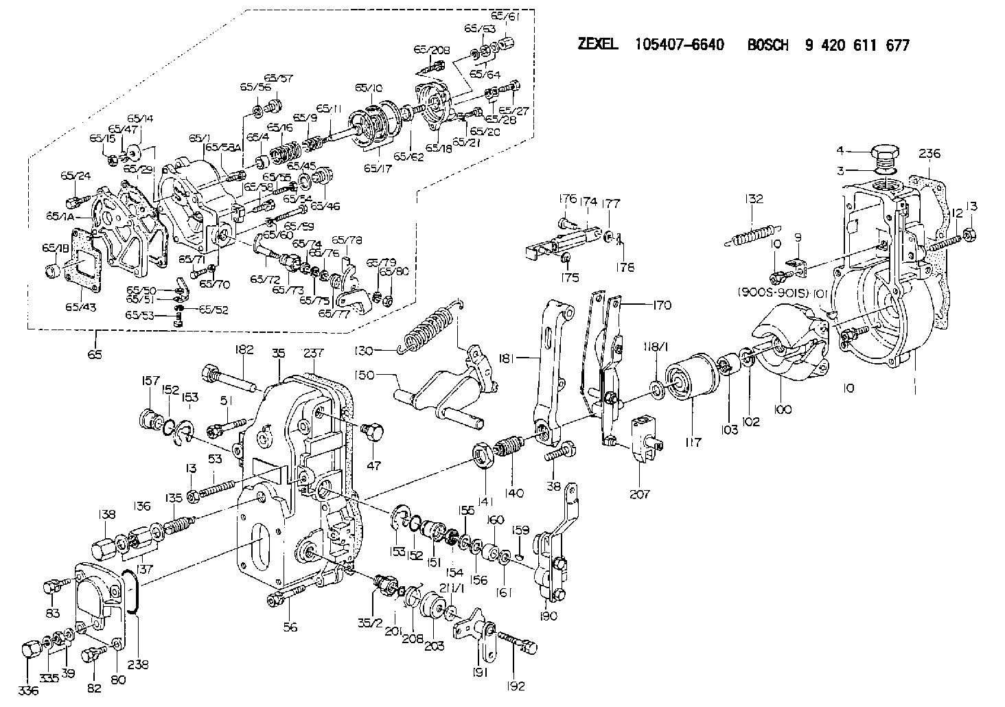
| 1. | [1] | 154000-4700 | GOVERNOR HOUSING |
| 3. | [1] | 029632-5070 | O-RING |
| 4. | [1] | 154007-2900 | CAPSULE |
| 9. | [1] | 154350-6000 | PLATE |
| 10. | [8] | 020106-2040 | BLEEDER SCREW M6P1L20 |
| 10. | [8] | 020106-2040 | BLEEDER SCREW M6P1L20 |
| 12. | [1] | 154010-1100 | FLAT-HEAD SCREW |
| 13. | [2] | 154011-0100 | HEXAGON NUT |
| 13. | [2] | 154011-0100 | HEXAGON NUT |
| 35. | [1] | 154500-8020 | GOVERNOR COVER |
| 35/2. | [1] | 154321-0400 | BUSHING |
| 38. | [1] | 154031-4300 | FLAT-HEAD SCREW |
| 39. | [1] | 139208-0400 | UNION NUT |
| 47. | [1] | 154036-0300 | CAPSULE |
| 51. | [2] | 020106-5040 | BLEEDER SCREW |
| 53. | [1] | 154010-0200 | FLAT-HEAD SCREW |
| 56. | [4] | 020106-3840 | BLEEDER SCREW |
| 65. | [1] | 154421-6521 | MANIFOLD-PRESSURE COMP. |
| 65/1. | [1] | 154412-9520 | GOVERNOR HOUSING |
| 65/1A. | [1] | 154412-0201 | SPACER BUSHING |
| 65/1B. | [1] | 134009-0000 | SPACER BUSHING |
| 65/4. | [1] | 154413-0500 | BUSHING |
| 65/9. | [1] | 154402-2600 | COILED SPRING |
| 65/10. | [1] | 154400-8220 | DIAPHRAGM |
| 65/11. | [1] | 154412-4101 | STOP PIN |
| 65/14. | [1] | 154406-5500 | SLOTTED WASHER |
| 65/15. | [1] | 013020-6040 | UNION NUT M6P1H5 |
| 65/16. | [1] | 154411-9000 | COILED SPRING |
| 65/17. | [2] | 154413-2600 | GASKET |
| 65/18. | [1] | 154404-5000 | COVER |
| 65/20. | [2] | 029010-6310 | BLEEDER SCREW |
| 65/20B. | [1] | 020106-4540 | BLEEDER SCREW M6P1.0L45 |
| 65/21. | [2] | 014110-6440 | LOCKING WASHER |
| 65/24. | [2] | 020106-2040 | BLEEDER SCREW M6P1L20 |
| 65/27. | [1] | 029731-0180 | EYE BOLT |
| 65/28. | [2] | 026510-1340 | GASKET D13.4&10.2T1 |
| 65/29. | [1] | 154390-2200 | GASKET |
| 65/43. | [1] | 154390-2300 | GASKET |
| 65/45. | [1] | 029331-8040 | GASKET |
| 65/46. | [1] | 154406-5800 | FLAT-HEAD SCREW |
| 65/47. | [1] | 014110-6440 | LOCKING WASHER |
| 65/50. | [1] | 154406-6800 | PLAIN WASHER |
| 65/51. | [1] | 154412-9800 | CONTROL LEVER |
| 65/52. | [1] | 014110-4440 | LOCKING WASHER |
| 65/53. | [1] | 010234-0820 | HEX-SOCKET-HEAD CAP SCREW |
| 65/54. | [1] | 013030-6040 | UNION NUT M6P1H3.6 |
| 65/55. | [1] | 154404-1500 | FLAT-HEAD SCREW L22.00 |
| 65/55B. | [1] | 154404-1600 | FLAT-HEAD SCREW L26.00 |
| 65/56. | [1] | 029331-2130 | GASKET |
| 65/57. | [1] | 154406-6500 | FLAT-HEAD SCREW |
| 65/58. | [2] | 020106-2840 | BLEEDER SCREW |
| 65/58A. | [1] | 020106-1440 | BLEEDER SCREW M6P1.0L14 |
| 65/59. | [1] | 010006-7040 | BLEEDER SCREW M6P1L70 |
| 65/60. | [1] | 014110-6440 | LOCKING WASHER |
| 65/61. | [1] | 154035-1600 | CAP NUT |
| 65/62. | [1] | 154404-4400 | FLAT-HEAD SCREW |
| 65/63. | [1] | 013030-6040 | UNION NUT M6P1H3.6 |
| 65/64. | [2] | 026506-1040 | GASKET D9.9&6.2T1 |
| 65/70. | [1] | 029240-6010 | UNION NUT M6P1.0H5* |
| 65/71. | [1] | 153141-1600 | BLEEDER SCREW |
| 65/72. | [1] | 154413-0021 | LEVER SHAFT |
| 65/73. | [1] | 154413-0100 | BUSHING |
| 65/74. | [1] | 139608-0000 | PACKING RING |
| 65/75. | [1] | 154413-0200 | PLAIN WASHER |
| 65/76. | [0] | 029310-8030 | SHIM D13.5&8T0.1 |
| 65/76B. | [0] | 029310-8040 | SHIM D13.5&8T0.2 |
| 65/77. | [1] | 154413-0301 | COILED SPRING |
| 65/78. | [1] | 154382-6900 | CONTROL LEVER |
| 65/79. | [1] | 014110-8440 | LOCKING WASHER |
| 65/80. | [1] | 013020-8140 | UNION NUT M8P1.25H6.5 |
| 80. | [1] | 154063-7300 | COVER |
| 82. | [2] | 029020-6210 | BLEEDER SCREW |
| 83. | [2] | 020006-1640 | BLEEDER SCREW M6P1L16 4T |
| 100. | [1] | 154101-0120 | FLYWEIGHT |
| 101. | [1] | 025803-1310 | WOODRUFF KEY |
| 102. | [1] | 029321-2020 | LOCKING WASHER |
| 103. | [1] | 029231-2030 | UNION NUT |
| 117. | [1] | 154123-2320 | SLIDING PIECE |
| 118/1. | [0] | 029311-0010 | SHIM D14&10.1T0.2 |
| 118/1. | [0] | 029311-0180 | SHIM D14&10.1T0.3 |
| 118/1. | [0] | 029311-0190 | SHIM D14&10.1T0.40 |
| 118/1. | [0] | 029311-0210 | SHIM D14&10.1T1 |
| 118/1. | [0] | 139410-0000 | SHIM D14.0&10.1T0.5 |
| 118/1. | [0] | 139410-0100 | SHIM D14.0&10.1T1.5 |
| 118/1. | [0] | 139410-3000 | SHIM D14&10.1T2.0 |
| 118/1. | [0] | 139410-3100 | SHIM D14&10.1T3.0 |
| 118/1. | [0] | 139410-3200 | SHIM D14&10.1T4.0 |
| 130. | [1] | 154150-2900 | GOVERNOR SPRING |
| 132. | [1] | 154154-0701 | COILED SPRING |
| 135. | [1] | 154158-0820 | HEADLESS SCREW |
| 136. | [1] | 154011-1700 | UNION NUT |
| 137. | [2] | 026512-1540 | GASKET D15.4&12.2T1.50 |
| 138. | [1] | 154159-1200 | CAP NUT |
| 140. | [1] | 154177-0520 | HEADLESS SCREW |
| 141. | [1] | 029201-6010 | UNION NUT |
| 150. | [1] | 154200-6920 | SWIVELLING LEVER |
| 151. | [1] | 154204-3000 | BUSHING |
| 152. | [2] | 029631-8020 | O-RING |
| 152. | [2] | 029631-8020 | O-RING |
| 153. | [2] | 016010-1640 | LOCKING WASHER |
| 153. | [2] | 016010-1640 | LOCKING WASHER |
| 154. | [1] | 139611-0000 | PACKING RING |
| 155. | [1] | 139411-0000 | SHIM |
| 156. | [0] | 029311-1070 | SHIM D16&11T0.5 |
| 157. | [1] | 154204-3100 | BUSHING |
| 159. | [1] | 025803-1310 | WOODRUFF KEY |
| 160. | [1] | 154206-2800 | BUSHING |
| 161. | [0] | 154206-0200 | PLAIN WASHER D19.5&11.2T1.0 |
| 170. | [1] | 154211-4420 | FORK LEVER |
| 174. | [1] | 154230-5120 | STRAP |
| 175. | [1] | 016010-0540 | LOCKING WASHER |
| 176. | [1] | 159231-4900 | BEARING PIN |
| 177. | [1] | 029310-5170 | SHIM D8&5.3T0.5 |
| 178. | [1] | 155402-3800 | SAFETY PIN |
| 181. | [1] | 154236-4100 | TENSIONING LEVER |
| 182. | [1] | 154237-1100 | BEARING PIN |
| 190. | [1] | 154347-1920 | CONTROL LEVER |
| 191. | [1] | 154381-6520 | CONTROL LEVER |
| 192. | [1] | 020006-4540 | BLEEDER SCREW M6P1L45 |
| 201. | [1] | 029631-0030 | O-RING &9.8W2.3 |
| 203. | [1] | 154322-0100 | CAP |
| 207. | [1] | 154326-5120 | CONTROL LEVER |
| 208. | [1] | 154327-7300 | COILED SPRING |
| 211/1. | [0] | 029311-0520 | SHIM D20.8&10.3T0.2 |
| 211/1. | [0] | 029311-0530 | SHIM D20.8&10.3T0.25 |
| 211/1. | [0] | 029311-0540 | SHIM D20.8&10.3T0.3 |
| 211/1. | [0] | 029311-0550 | SHIM D20.8&10.3T0.35 |
| 211/1. | [0] | 029311-0560 | SHIM D20.8&10.3T0.4 |
| 211/1. | [0] | 029311-0570 | SHIM D20.8&10.3T0.5 |
| 236. | [1] | 154371-5600 | GASKET |
| 237. | [1] | 154390-0300 | GASKET |
| 238. | [1] | 029635-2020 | O-RING |
| 335. | [2] | 026508-1140 | GASKET D11.4&8.2T1 |
| 336. | [1] | 154035-2000 | CAP NUT |
| 900S. | [1] | 025803-1310 | WOODRUFF KEY |
| 901S. | [1] | 025803-1610 | WOODRUFF KEY |
Cross reference number
Zexel num
Bosch num
Firm num
Name
105407-6640
ME742300 MITSUBISHI
GOVERNOR
A K 14JB MECHANICAL GOVERNOR GOV RSV GOV
A K 14JB MECHANICAL GOVERNOR GOV RSV GOV
Information:
No-load testAlternator
If a problem occurs in the charge system, check the following conditions to locate the cause of the problem. Only when inspection cannot be conducted on the alternator in the installed condition, dismount the alternator for inspection and repair. On Vehicle Inspection
(1) Cautions for handlingHandle the alternator carefully, as incorrect handling can result in alternator damage or malfunctions.(a) Do not connect the battery cables in reverse. Note the negative (-) cable is a grounding wire.(b) Do not use a high-voltage tester such as a megger.(c) When charging the battery, disconnect the cables from the battery terminals.(d) Do not disconnect the lead wire from terminal B of the alternator while the engine is operating.(e) Do not ground terminal B of the alternator since it is constantly applied with battery voltage.(f) Do not short-circuit or ground terminal L. (unit with integrated IC regulator)(g) When using a steam cleaner, do not allow steam to directly contact the alternator.(2) Inspection of adjustment voltage (unit with integrated IC regulator)(a) Disconnect the cable from the positive (+) terminal of the battery, and connect an ammeter between the terminal and cable.(b) Connect a voltmeter between terminal L and ground.(c) Make sure that the voltmeter indicates "0" when the starter switch is turned off. Make sure that the voltmeter indicates a voltage level significantly lower than the battery voltage when the starter switch is turned on (without starting the engine).(d) Short-circuit the terminal of the ammeter, and start the engine.(e) Read the indication (adjustment voltage) on the voltmeter with the ammeter indicating 5A or lower, the engine operating at 1500 to 2500 min-1, and the lamp switches turned off.
Inspection of adjustment voltage (3) Inspection of output (unit with integrated IC regulator)(a) Disconnect the grounding cable from the battery.(b) Disconnect the wire from terminal B of the alternator, and connect an ammeter, then connect a voltmeter between B and ground.(c) Reconnect the grounding cable to the battery.(d) Start the engine.(e) Immediately after the engine starts, turn on all load devices such as lamps.(f) Increase the engine speed, and read the maximum current at the specified alternator rotation speed when the voltmeter indicates 27.0 V. If the measured value conforms to the standard value, the alternator is normal.
Wiring for output test Disassembly of Alternator
(1) Separation of front bracket from stator coreInsert the tip of a slotted screwdriver into the gap between the stator core and front bracket, and pry open.
Do not insert the screwdriver too far into the assembly to prevent damaging the stator core.
Separation of front bracket from stator core(2) Removal of pulley(a) After wrapping the rotor with a cloth for protection and holding it with a vice, unscrew the pulley nut, then remove the pulley and spacer.(b) Remove the rotor from the front bracket.
Removal of pulley(3) Removal of stator core and rectifier(a) Disconnect the lead wires between the stator core and the rectifier at the soldered sections, and remove the stator core.
Melt the soldered sections as quickly as possible. Prolonged heating cam damage the diodes.
(b)