Information governor
BOSCH
9 420 611 009
9420611009
ZEXEL
105407-6460
1054076460
MITSUBISHI
ME742179
me742179
Rating:
Scheme ###:
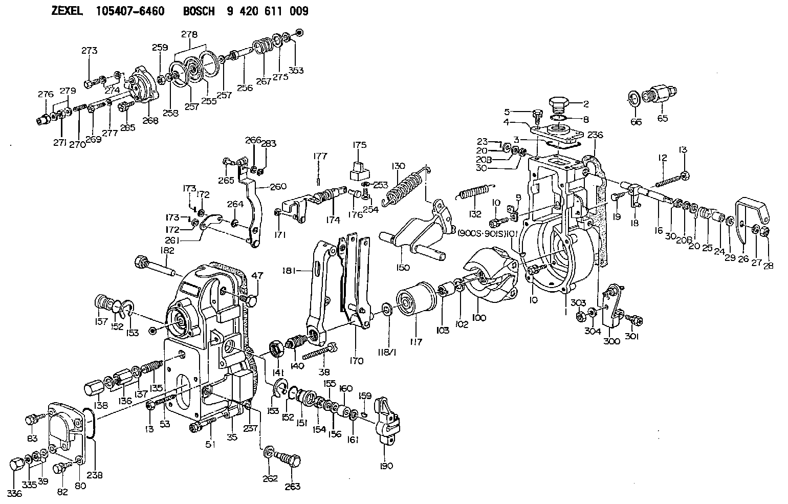
| 1. | [1] | 154004-2822 | GOVERNOR HOUSING |
| 2. | [1] | 154007-2900 | CAPSULE |
| 3. | [1] | 154358-2500 | SEAL RING |
| 4. | [1] | 154063-7900 | COVER |
| 5. | [4] | 020006-1640 | BLEEDER SCREW M6P1L16 4T |
| 8. | [1] | 029632-5070 | O-RING |
| 9. | [1] | 154350-6000 | PLATE |
| 10. | [8] | 020106-2040 | BLEEDER SCREW M6P1L20 |
| 10. | [8] | 020106-2040 | BLEEDER SCREW M6P1L20 |
| 12. | [1] | 154010-1100 | FLAT-HEAD SCREW |
| 13. | [2] | 154011-0100 | HEXAGON NUT |
| 13. | [2] | 154011-0100 | HEXAGON NUT |
| 16. | [1] | 155004-3600 | LEVER SHAFT |
| 18. | [1] | 155003-2101 | CONTROL LEVER |
| 19. | [1] | 155006-0700 | BLEEDER SCREW |
| 20. | [1] | 139308-0900 | PLAIN WASHER D16&8T1 |
| 20. | [1] | 139308-0900 | PLAIN WASHER D16&8T1 |
| 20B. | [1] | 139308-1000 | PLAIN WASHER D16&8T1.5 |
| 20B. | [1] | 139308-1000 | PLAIN WASHER D16&8T1.5 |
| 23. | [1] | 025520-1210 | SPLIT PIN |
| 24. | [1] | 154206-2000 | BUSHING |
| 25. | [1] | 154327-4200 | COILED SPRING |
| 26. | [1] | 154381-7900 | CONTROL LEVER |
| 27. | [1] | 014110-8440 | LOCKING WASHER |
| 28. | [1] | 013020-8040 | UNION NUT M8P1.25H7 |
| 29. | [1] | 139408-1500 | SHIM |
| 29B. | [0] | 139408-1400 | SHIM |
| 29C. | [0] | 139408-1500 | SHIM |
| 30. | [2] | 029620-8050 | PACKING RING |
| 30. | [2] | 029620-8050 | PACKING RING |
| 35. | [1] | 154022-7920 | GOVERNOR COVER |
| 38. | [1] | 154031-1300 | FLAT-HEAD SCREW |
| 39. | [1] | 139206-0600 | UNION NUT |
| 47. | [1] | 154036-0300 | CAPSULE |
| 51. | [6] | 020106-5040 | BLEEDER SCREW |
| 53. | [1] | 154010-0200 | FLAT-HEAD SCREW |
| 65. | [1] | 153021-2220 | STOPPING DEVICE |
| 66. | [1] | 026524-3040 | GASKET |
| 80. | [1] | 154063-1400 | COVER |
| 82. | [2] | 029020-6210 | BLEEDER SCREW |
| 83. | [2] | 020006-1640 | BLEEDER SCREW M6P1L16 4T |
| 100. | [1] | 154101-0020 | FLYWEIGHT ASSEMBLY |
| 101. | [1] | 025803-1310 | WOODRUFF KEY |
| 102. | [1] | 029321-2020 | LOCKING WASHER |
| 103. | [1] | 029231-2030 | UNION NUT |
| 117. | [1] | 154123-2320 | SLIDING PIECE |
| 118/1. | [0] | 029311-0010 | SHIM D14&10.1T0.2 |
| 118/1. | [0] | 029311-0180 | SHIM D14&10.1T0.3 |
| 118/1. | [0] | 029311-0190 | SHIM D14&10.1T0.40 |
| 118/1. | [0] | 029311-0210 | SHIM D14&10.1T1 |
| 118/1. | [0] | 139410-0000 | SHIM D14.0&10.1T0.5 |
| 118/1. | [0] | 139410-0100 | SHIM D14.0&10.1T1.5 |
| 118/1. | [0] | 139410-3000 | SHIM D14&10.1T2.0 |
| 118/1. | [0] | 139410-3100 | SHIM D14&10.1T3.0 |
| 118/1. | [0] | 139410-3200 | SHIM D14&10.1T4.0 |
| 132. | [1] | 154154-0500 | COILED SPRING |
| 135. | [1] | 154158-0820 | HEADLESS SCREW |
| 136. | [1] | 029201-2290 | UNION NUT |
| 137. | [2] | 026512-1540 | GASKET D15.4&12.2T1.50 |
| 138. | [1] | 154159-1200 | CAP NUT |
| 140. | [1] | 154185-2120 | HEADLESS SCREW |
| 141. | [1] | 029201-6010 | UNION NUT |
| 150. | [1] | 154200-6920 | SWIVELLING LEVER |
| 151. | [1] | 154204-3000 | BUSHING |
| 152. | [2] | 029631-8020 | O-RING |
| 152. | [2] | 029631-8020 | O-RING |
| 153. | [2] | 016010-1640 | LOCKING WASHER |
| 153. | [2] | 016010-1640 | LOCKING WASHER |
| 154. | [1] | 139611-0000 | PACKING RING |
| 155. | [1] | 139411-0000 | SHIM |
| 156. | [0] | 029311-1070 | SHIM D16&11T0.5 |
| 157. | [1] | 154204-3100 | BUSHING |
| 159. | [1] | 025803-1310 | WOODRUFF KEY |
| 160. | [1] | 154206-2800 | BUSHING |
| 161. | [0] | 154206-0200 | PLAIN WASHER D19.5&11.2T1.0 |
| 170. | [1] | 154217-2920 | FORK LEVER |
| 171. | [1] | 016010-0540 | LOCKING WASHER |
| 172. | [4] | 029310-5170 | SHIM D8&5.3T0.5 |
| 172. | [4] | 029310-5170 | SHIM D8&5.3T0.5 |
| 173. | [3] | 025520-1210 | SPLIT PIN |
| 173. | [3] | 025520-1210 | SPLIT PIN |
| 174. | [1] | 154234-6920 | STRAP |
| 175. | [1] | 154232-2420 | CONNECTOR |
| 176. | [1] | 159231-4900 | BEARING PIN |
| 177. | [1] | 155402-3800 | SAFETY PIN |
| 181. | [1] | 154239-3320 | TENSIONING LEVER |
| 182. | [1] | 154237-1100 | BEARING PIN |
| 190. | [1] | 154340-0120 | CONTROL LEVER |
| 236. | [1] | 154371-5600 | GASKET |
| 237. | [1] | 154390-0300 | GASKET |
| 238. | [1] | 029635-2020 | O-RING |
| 253. | [1] | 029320-5020 | LOCKING WASHER |
| 254. | [1] | 010535-1040 | FLAT-HEAD SCREW M5P0.8L10 |
| 255. | [1] | 154400-7420 | DIAPHRAGM |
| 256. | [1] | 154400-4800 | STOP PIN |
| 257. | [2] | 029330-8050 | GASKET |
| 257. | [2] | 029330-8050 | GASKET |
| 258. | [1] | 139308-0700 | LOCKING WASHER |
| 259. | [1] | 013030-6040 | UNION NUT M6P1H3.6 |
| 260. | [1] | 154401-3620 | CONTROL LEVER |
| 261. | [1] | 154401-1320 | STRAP |
| 262. | [1] | 026510-1440 | GASKET D13.9&10.2T1 |
| 263. | [1] | 154401-2100 | BLEEDER SCREW |
| 264. | [1] | 016010-0540 | LOCKING WASHER |
| 265. | [1] | 154222-6200 | BEARING PIN |
| 266. | [1] | 029300-4010 | PLAIN WASHER |
| 267. | [1] | 154416-0600 | COILED SPRING |
| 268. | [1] | 154404-5000 | COVER |
| 269. | [2] | 020106-2540 | BLEEDER SCREW M6P1L25 |
| 270. | [1] | 154034-1900 | FLAT-HEAD SCREW |
| 271. | [1] | 013030-6040 | UNION NUT M6P1H3.6 |
| 273. | [1] | 029731-0180 | EYE BOLT |
| 274. | [2] | 026510-1340 | GASKET D13.4&10.2T1 |
| 275. | [0] | 029312-0180 | SHIM D25.5&20T0.5 |
| 275B. | [0] | 029312-0210 | SHIM D25.5&20T0.2 |
| 276. | [1] | 154035-1900 | CAP NUT |
| 277. | [1] | 014110-6440 | LOCKING WASHER |
| 278. | [2] | 154413-2600 | GASKET |
| 279. | [2] | 026506-1040 | GASKET D9.9&6.2T1 |
| 283. | [1] | 016010-0440 | LOCKING WASHER |
| 285. | [1] | 029010-6310 | BLEEDER SCREW |
| 300. | [1] | 154358-9420 | BRACKET |
| 301. | [1] | 020118-1640 | BLEEDER SCREW |
| 303. | [1] | 154011-1100 | UNION NUT |
| 304. | [1] | 029300-8320 | SHIM |
| 335. | [2] | 026506-1040 | GASKET D9.9&6.2T1 |
| 336. | [1] | 154035-1600 | CAP NUT |
| 353. | [4] | 029310-9080 | SHIM D16&9T1.7 |
| 900S. | [1] | 025803-1310 | WOODRUFF KEY |
| 901S. | [1] | 025803-1610 | WOODRUFF KEY |
Cross reference number
Zexel num
Bosch num
Firm num
Name
105407-6460
ME742179 MITSUBISHI
GOVERNOR
K 14JB MECHANICAL GOVERNOR GOV RSV GOV
K 14JB MECHANICAL GOVERNOR GOV RSV GOV
Information:
Governor Actuator Mounting Replacement:
Removal Of The Previous Assembly
1. Disconnect linkage from cylinder and fuel pump, disassemble bracket from fuel pump lever.2. Remove cylinder from mounting plate, twist out rod end from cylinder.3. Remove mounting plate.Installing Of The New Linkage
1. Install 1433909, 8T4908, 8T4224, 9X6032, 8T4121 Linkage Assembly to engine block.2. Screw in U-joint of 1233885 Cylinder Rod as close as possible, tighten with 1426000 Nut, assemble cylinder with 8T1160 Bolts to the hinge.3. Assemble lever with washer and lock nut (1392085, 8T0389, 1392082, 8T4121), check free movement.4. Disconnect electrical connector from cylinder, turn on ignition, so that cylinder extends.5. Ensure pre-adjustment (overlapping of 1 mm) of U-joint and lever using the 8T4195 Stop Screw; tighten screw with nut (8T4133); See Illustration 2.6. Connect electrical connector to the cylinder and link up rod and lever with the 1233884 Pin.
Illustration 2Calibration
All adjustments have to be done with machine / engine at operating temperature
1. Start the engine.2. Plug-in PDT (portable diagnostic tool), choose menu "PROC" number 5 "ENGINE RPM" and number 6 "RPM DIFFERENCE". High And Low Idle Adjustment At Injection Pump:
1. Actuate the lever of the fuel injection pump by hand and adjust high and low idle by turning the corresponding stop screw at the fuel injection pump. If necessary fix the lever in the high idle position by use of a light spring to make adjustment easier:Set low idle to: 750 Rpm -20/+0 RpmSet high idle to : 2400 Rpm -0/+20 Rpm2. Make sure that when this is set a 1 mm spacer is fitted between the throttle lever and the high idle adjustment screw (see Illustration 3).3. Secure stop screw with locking nut. Seal setting with lockwire and lead seal, use your CAT dealer identification pliers.4. Disconnect electrical connector from the actuator (actuator piston extends completely).5. Stop the engine.6. Assemble and connect the 1413978 or 1397394, 9X8256, 1400277, 6V7743, 5C2890, 1107299, 1396903 Adjustable Rod, use the center hole at the fuel injection pump lever. Make sure that there is no contact between the fuel injection pump lever and the stop screw at high idle position.7. Start the engine.8. Adjust high idle setting with the rod:M312: high idle 2150 Rpm -0/+20 Rpm.M315: high idle 2400 Rpm -0/+20 Rpm.9. Secure the rod with the nuts at the ball joints.10. Mark the lock nut positions at the ball joints with a paint dot or using a felt-tip pen.11. Connect the electrical connector to the actuator.
Illustration 3Calibration/Adjustment Of The Engine
1. Press "F 1" key at the PDT for calibration.2. Choose item number 2 "CALIBRATION".3. Choose item number 1 "SPEED DIAL CAL".4. "MIN POSITION" setting, turn potentiometer on the panel until you receive the minimum voltage shown in the screen, press "ENTER".5. "MAX POSITION" setting, turn potentiometer until you receive maximum voltage shown in the screen, press "ENTER".6. You automatically get back into the previous menu, now choose number 2 "SPEED CAL".7. Change the low idle setting to 1020 Rpm by using the "UP- "or "DOWN-ARROW" keys at the PDT, when finished,