Information governor
BOSCH
9 420 610 722
9420610722
ZEXEL
105407-6311
1054076311
YANMAR
12662551160
12662551160
Rating:
Scheme ###:
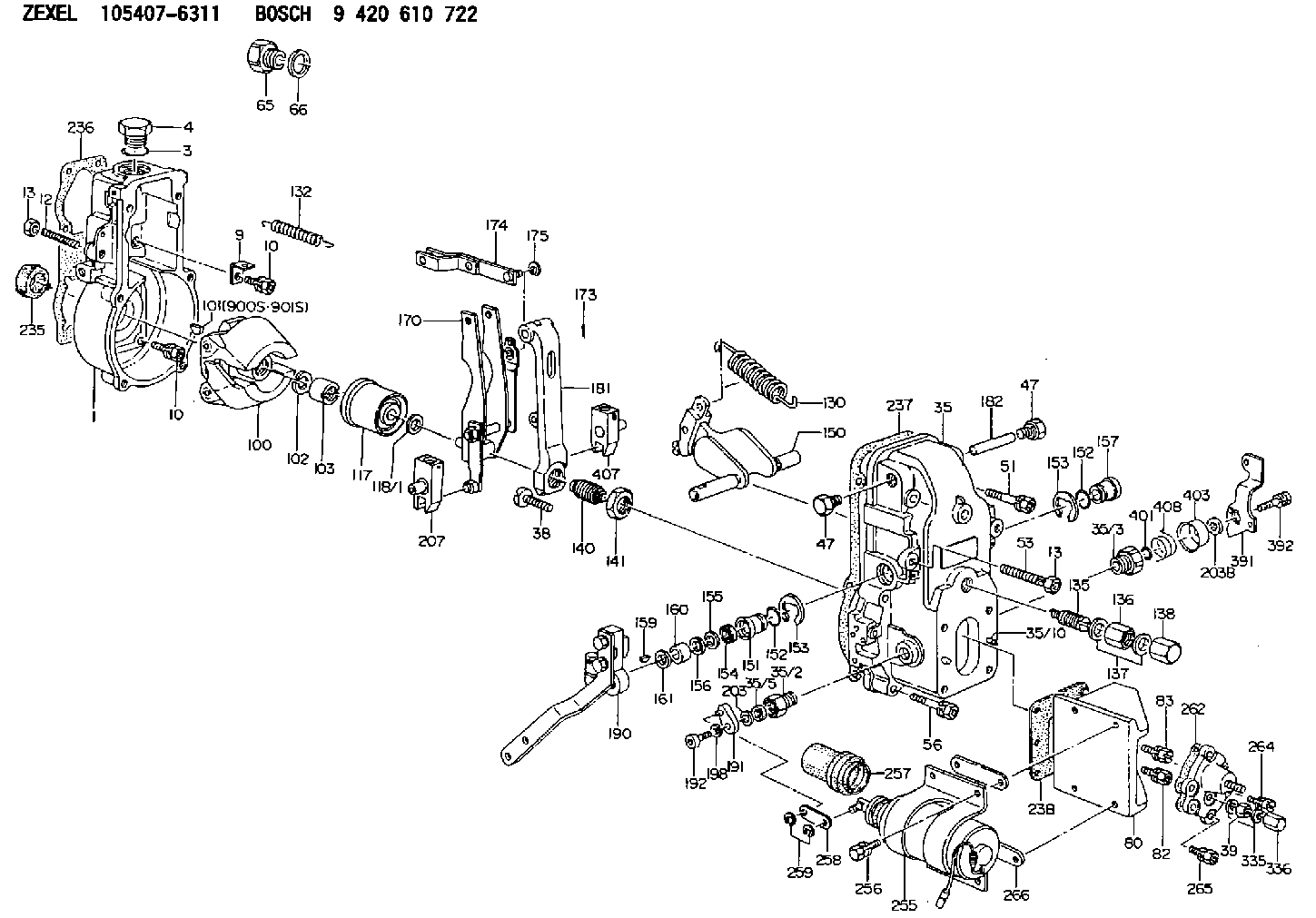
| 1. | [1] | 154000-5720 | GOVERNOR HOUSING |
| 3. | [1] | 029632-5070 | O-RING |
| 4. | [1] | 154007-2900 | CAPSULE |
| 9. | [1] | 154350-6000 | PLATE |
| 10. | [8] | 020106-2040 | BLEEDER SCREW M6P1L20 |
| 10. | [8] | 020106-2040 | BLEEDER SCREW M6P1L20 |
| 12. | [1] | 154010-0500 | FLAT-HEAD SCREW |
| 13. | [2] | 154011-0100 | HEXAGON NUT |
| 13. | [2] | 154011-0100 | HEXAGON NUT |
| 35. | [1] | 154500-4620 | GOVERNOR COVER |
| 35/2. | [1] | 154321-0400 | BUSHING |
| 35/3. | [1] | 154321-1300 | BUSHING |
| 35/5. | [1] | 029621-0010 | PACKING RING |
| 35/10. | [2] | 015060-1480 | BEARING PIN |
| 38. | [1] | 154031-5700 | FLAT-HEAD SCREW |
| 39. | [1] | 139206-0600 | UNION NUT |
| 47. | [2] | 154036-0300 | CAPSULE |
| 47. | [2] | 154036-0300 | CAPSULE |
| 51. | [2] | 020106-5040 | BLEEDER SCREW |
| 53. | [1] | 154010-0500 | FLAT-HEAD SCREW |
| 56. | [4] | 020106-3840 | BLEEDER SCREW |
| 65. | [1] | 155404-1700 | CAP |
| 66. | [1] | 026524-3040 | GASKET |
| 80. | [1] | 154063-1300 | COVER |
| 82. | [2] | 029010-6540 | BLEEDER SCREW |
| 83. | [2] | 020106-2840 | BLEEDER SCREW |
| 100. | [1] | 154101-0020 | FLYWEIGHT ASSEMBLY |
| 101. | [1] | 025803-1310 | WOODRUFF KEY |
| 102. | [1] | 029321-2020 | LOCKING WASHER |
| 103. | [1] | 029231-2030 | UNION NUT |
| 117. | [1] | 154123-0120 | SLIDING PIECE |
| 118/1. | [0] | 029311-0010 | SHIM D14&10.1T0.2 |
| 118/1. | [0] | 029311-0180 | SHIM D14&10.1T0.3 |
| 118/1. | [0] | 029311-0190 | SHIM D14&10.1T0.40 |
| 118/1. | [0] | 029311-0210 | SHIM D14&10.1T1 |
| 118/1. | [0] | 139410-0000 | SHIM D14.0&10.1T0.5 |
| 118/1. | [0] | 139410-0100 | SHIM D14.0&10.1T1.5 |
| 118/1. | [0] | 139410-3000 | SHIM D14&10.1T2.0 |
| 118/1. | [0] | 139410-3100 | SHIM D14&10.1T3.0 |
| 118/1. | [0] | 139410-3200 | SHIM D14&10.1T4.0 |
| 130. | [1] | 154150-0200 | GOVERNOR SPRING |
| 132. | [1] | 154154-0800 | COILED SPRING |
| 135. | [1] | 154158-1020 | HEADLESS SCREW |
| 136. | [1] | 154011-2700 | UNION NUT |
| 137. | [2] | 026512-1540 | GASKET D15.4&12.2T1.50 |
| 138. | [1] | 154159-1200 | CAP NUT |
| 140. | [1] | 154185-1320 | HEADLESS SCREW |
| 141. | [1] | 029201-6010 | UNION NUT |
| 150. | [1] | 154200-7020 | SWIVELLING LEVER |
| 151. | [1] | 154204-3000 | BUSHING |
| 152. | [2] | 029631-8020 | O-RING |
| 152. | [2] | 029631-8020 | O-RING |
| 153. | [2] | 016010-1640 | LOCKING WASHER |
| 153. | [2] | 016010-1640 | LOCKING WASHER |
| 154. | [1] | 139611-0000 | PACKING RING |
| 155. | [1] | 139411-0000 | SHIM |
| 156. | [0] | 029311-1090 | SHIM D16&11T0.3 |
| 157. | [1] | 154204-3100 | BUSHING |
| 159. | [1] | 025803-1310 | WOODRUFF KEY |
| 160. | [1] | 154206-2800 | BUSHING |
| 161. | [0] | 154206-0200 | PLAIN WASHER D19.5&11.2T1.0 |
| 170. | [1] | 154217-0720 | FORK LEVER |
| 173. | [1] | 025520-1210 | SPLIT PIN |
| 174. | [1] | 154230-2920 | STRAP |
| 175. | [1] | 016010-0540 | LOCKING WASHER |
| 181. | [1] | 154236-4100 | TENSIONING LEVER |
| 182. | [1] | 154237-0100 | BEARING PIN |
| 190. | [1] | 154345-4920 | CONTROL LEVER |
| 191. | [1] | 154307-9420 | CONTROL LEVER |
| 192. | [1] | 010206-1440 | HEX-SOCKET-HEAD CAP SCREW M6P1L14 |
| 198. | [1] | 029320-6010 | LOCKING WASHER |
| 203. | [0] | 029311-0220 | SHIM D18&10.3T0.2 |
| 203B. | [0] | 029311-0230 | SHIM D18&10.3T0.5 |
| 207. | [1] | 154326-5020 | CONTROL LEVER |
| 235. | [1] | 155412-5200 | IMPELLER WHEEL |
| 236. | [1] | 154371-5600 | GASKET |
| 237. | [1] | 154390-0300 | GASKET |
| 238. | [1] | 154351-1400 | GASKET |
| 255. | [1] | 154409-9820 | SOLENOID |
| 256. | [4] | 020006-1440 | BLEEDER SCREW M6P1L14 |
| 257. | [1] | 154409-8400 | COVER |
| 258. | [1] | 154409-9000 | STRAP |
| 259. | [2] | 016010-0510 | LOCKING WASHER |
| 262. | [1] | 154353-5700 | GASKET |
| 264. | [1] | 029020-6260 | BLEEDER SCREW |
| 265. | [5] | 020106-2040 | BLEEDER SCREW M6P1L20 |
| 266. | [0] | 154351-2000 | SHIM T0.20 |
| 266B. | [0] | 154351-2100 | SHIM T0.50 |
| 266C. | [0] | 154351-2200 | SHIM T1.00 |
| 335. | [2] | 026506-1040 | GASKET D9.9&6.2T1 |
| 336. | [1] | 154035-1900 | CAP NUT |
| 391. | [1] | 154304-4720 | CONTROL LEVER |
| 392. | [1] | 020006-1640 | BLEEDER SCREW M6P1L16 4T |
| 401. | [1] | 029631-0030 | O-RING &9.8W2.3 |
| 403. | [1] | 154322-0100 | CAP |
| 407. | [1] | 154324-2820 | CONTROL LEVER |
| 408. | [1] | 154327-7300 | COILED SPRING |
| 900S. | [1] | 025803-1310 | WOODRUFF KEY |
| 901S. | [1] | 025803-1610 | WOODRUFF KEY |
Include in #1:
106692-9381
as GOVERNOR
Cross reference number
Zexel num
Bosch num
Firm num
Name
105407-6311
12662551160 YANMAR
GOVERNOR
K 14JB MECHANICAL GOVERNOR GOV RSV GOV
K 14JB MECHANICAL GOVERNOR GOV RSV GOV
Information:
Cooling System
The centrifugal-type water pump mounts on the front cover and is belt driven by the crankshaft pulley. The pump has two outlets. Coolant from the outlet on the right side of the pump flows through a passage in the front cover to the left bank of the engine, and coolant from the outlet on the left flows to the right bank.The coolant circulates through the block to the cylinder head. Coolant flows from the heads through connecting sleeves to the return manifold in the front cover. Orifices in the sleeves control the flow from the heads.Part of the coolant to the left bank is diverted from the block to the oil cooler. External lines direct coolant from the block to the cooler and back to the return manifold in the front cover.An internal passage in the front cover directs the coolant from the return manifold to the water pump inlet. If the thermostats are closed the coolant flows to the pump and is recirculated through the engine. If they are open, coolant flows from the return manifold to the radiator and from there to the pump.The radiator is constructed with a top tank above the core and an expansion tank either above or separate from the top tank. A vent tube connects the radiator top tank and the expansion tank. The expansion tank has a shunt line which connects to the water pump inlet. This shunt system maintains a positive, static head of coolant at the pump inlet to prevent cavitation under all operating conditions. When filling the cooling system, coolant from the expansion tank flows through the shunt line to the water pump inlet and fills the engine block from the bottom. By filling the system from the bottom, air in the system is forced out through the top tank, through the vent tube into the expansion tank.The two thermostats are located at the inlet to the water pump. The inlet-regulated cooling system maintains positive coolant temperature control with decreased engine warm up time.When the thermostats are closed, coolant is circulated through the block and heads and back to the water pump by way of an internal passage in the front cover. When the thermostats are open, the bypass flow is restricted and the engine coolant flows through the radiator and returns through the inlet elbow to the water pump. Without the thermostats installed, the coolant will continually bypass the radiator, and overheating will result.Electrical System
The electrical system is a combination of three separate electric circuits: the charging circuit, the starting circuit and the lighting or load circuit. Each circuit is dependent on some of the same components. The battery (batteries), disconnect switch, circuit breaker, ammeter, cables and wires from the battery are common in each of the circuits.The charging circuit is in operation when the engine is operating. The electricity producing (charging) unit is an alternator. A regulator in the circuit senses the state of charge in the battery and regulates the electrical output to