Information governor
BOSCH
9 420 610 913
9420610913
ZEXEL
105407-6300
1054076300
HINO
223204150A
223204150a
Rating:
Scheme ###:
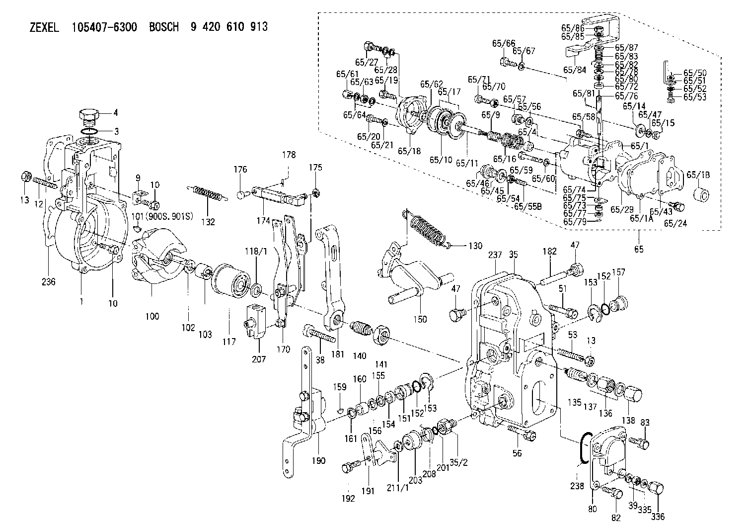
| 1. | [1] | 154000-4700 | GOVERNOR HOUSING |
| 3. | [1] | 029632-5070 | O-RING |
| 4. | [1] | 154007-2900 | CAPSULE |
| 9. | [1] | 154350-6000 | PLATE |
| 10. | [8] | 020106-2040 | BLEEDER SCREW M6P1L20 |
| 10. | [8] | 020106-2040 | BLEEDER SCREW M6P1L20 |
| 12. | [1] | 154010-1100 | FLAT-HEAD SCREW |
| 13. | [2] | 154011-0100 | HEXAGON NUT |
| 13. | [2] | 154011-0100 | HEXAGON NUT |
| 35. | [1] | 154500-1020 | GOVERNOR COVER |
| 35/2. | [1] | 154321-0400 | BUSHING |
| 38. | [1] | 154031-2400 | FLAT-HEAD SCREW |
| 39. | [1] | 139206-0600 | UNION NUT |
| 47. | [2] | 154036-0300 | CAPSULE |
| 47. | [2] | 154036-0300 | CAPSULE |
| 51. | [2] | 020106-5040 | BLEEDER SCREW |
| 53. | [1] | 154010-0500 | FLAT-HEAD SCREW |
| 56. | [4] | 020106-3840 | BLEEDER SCREW |
| 65. | [1] | 154421-5320 | MANIFOLD-PRESSURE COMP. |
| 65/1. | [1] | 154412-7820 | DIAPHRAGM HOUSING |
| 65/1A. | [1] | 154408-2901 | SPACER BUSHING |
| 65/1B. | [1] | 134009-0000 | SPACER BUSHING |
| 65/4. | [1] | 154413-0500 | BUSHING |
| 65/9. | [1] | 154412-4300 | COILED SPRING |
| 65/10. | [1] | 154400-8220 | DIAPHRAGM |
| 65/11. | [1] | 154400-6101 | STOP PIN |
| 65/14. | [1] | 154406-5500 | SLOTTED WASHER |
| 65/15. | [1] | 013020-6040 | UNION NUT M6P1H5 |
| 65/16. | [1] | 154416-2700 | COILED SPRING |
| 65/17. | [2] | 154413-2600 | GASKET |
| 65/18. | [1] | 154404-5000 | COVER |
| 65/19. | [1] | 020106-2040 | BLEEDER SCREW M6P1L20 |
| 65/20. | [2] | 029010-6310 | BLEEDER SCREW |
| 65/21. | [2] | 014110-6440 | LOCKING WASHER |
| 65/24. | [2] | 020106-2040 | BLEEDER SCREW M6P1L20 |
| 65/27. | [1] | 029731-0180 | EYE BOLT |
| 65/28. | [2] | 026510-1340 | GASKET D13.4&10.2T1 |
| 65/29. | [1] | 154390-1700 | GASKET |
| 65/43. | [1] | 154390-1800 | GASKET |
| 65/45. | [1] | 029331-8040 | GASKET |
| 65/46. | [1] | 154406-5800 | FLAT-HEAD SCREW |
| 65/47. | [1] | 014110-6440 | LOCKING WASHER |
| 65/50. | [1] | 154406-6800 | PLAIN WASHER |
| 65/51. | [1] | 154406-6901 | CONTROL LEVER |
| 65/52. | [1] | 014110-4440 | LOCKING WASHER |
| 65/53. | [1] | 010234-0820 | HEX-SOCKET-HEAD CAP SCREW |
| 65/54. | [1] | 013030-6040 | UNION NUT M6P1H3.6 |
| 65/55B. | [1] | 154404-1600 | FLAT-HEAD SCREW L26.00 |
| 65/56. | [1] | 029331-2130 | GASKET |
| 65/57. | [1] | 154406-6500 | FLAT-HEAD SCREW |
| 65/58. | [1] | 020106-2540 | BLEEDER SCREW M6P1L25 |
| 65/59. | [2] | 010006-7040 | BLEEDER SCREW M6P1L70 |
| 65/60. | [2] | 014110-6440 | LOCKING WASHER |
| 65/61. | [1] | 154035-1600 | CAP NUT |
| 65/62. | [1] | 154404-4400 | FLAT-HEAD SCREW |
| 65/63. | [1] | 013030-6040 | UNION NUT M6P1H3.6 |
| 65/64. | [2] | 026506-1040 | GASKET D9.9&6.2T1 |
| 65/66. | [1] | 139006-0900 | BLEEDER SCREW |
| 65/67. | [1] | 014110-6440 | LOCKING WASHER |
| 65/70. | [1] | 029240-6010 | UNION NUT M6P1.0H5* |
| 65/71. | [1] | 153141-1600 | BLEEDER SCREW |
| 65/72. | [1] | 139608-0000 | PACKING RING |
| 65/73. | [1] | 139605-0100 | PACKING RING |
| 65/74. | [1] | 154408-9000 | CONTROL LEVER |
| 65/75. | [1] | 154406-7500 | CONTROL LEVER |
| 65/76. | [1] | 154406-8000 | LEVER SHAFT |
| 65/77. | [1] | 029310-5200 | SHIM |
| 65/78. | [1] | 014020-8120 | PLAIN WASHER D16&8.5T1.2 |
| 65/79. | [1] | 154372-6500 | SAFETY PIN |
| 65/80. | [0] | 029310-8040 | SHIM D13.5&8T0.2 |
| 65/80B. | [0] | 029310-8050 | SHIM D13.5&8T0.5 |
| 65/81. | [1] | 025520-1210 | SPLIT PIN |
| 65/82. | [2] | 029300-8320 | SHIM |
| 65/83. | [1] | 154403-9900 | COILED SPRING |
| 65/84. | [1] | 154413-6700 | CONTROL LEVER |
| 65/85. | [1] | 139308-1800 | PLAIN WASHER |
| 65/86. | [1] | 013020-8140 | UNION NUT M8P1.25H6.5 |
| 65/87. | [1] | 139308-1800 | PLAIN WASHER |
| 80. | [1] | 154063-1400 | COVER |
| 82. | [2] | 029020-6210 | BLEEDER SCREW |
| 83. | [2] | 020006-1640 | BLEEDER SCREW M6P1L16 4T |
| 100. | [1] | 154101-0020 | FLYWEIGHT ASSEMBLY |
| 101. | [1] | 025803-1310 | WOODRUFF KEY |
| 102. | [1] | 029321-2020 | LOCKING WASHER |
| 103. | [1] | 029231-2030 | UNION NUT |
| 117. | [1] | 154123-0120 | SLIDING PIECE |
| 118/1. | [0] | 029311-0010 | SHIM D14&10.1T0.2 |
| 118/1. | [0] | 029311-0180 | SHIM D14&10.1T0.3 |
| 118/1. | [0] | 029311-0190 | SHIM D14&10.1T0.40 |
| 118/1. | [0] | 029311-0210 | SHIM D14&10.1T1 |
| 118/1. | [0] | 139410-0000 | SHIM D14.0&10.1T0.5 |
| 118/1. | [0] | 139410-0100 | SHIM D14.0&10.1T1.5 |
| 118/1. | [0] | 139410-3000 | SHIM D14&10.1T2.0 |
| 118/1. | [0] | 139410-3100 | SHIM D14&10.1T3.0 |
| 118/1. | [0] | 139410-3200 | SHIM D14&10.1T4.0 |
| 130. | [1] | 154150-0400 | GOVERNOR SPRING |
| 132. | [1] | 154154-0701 | COILED SPRING |
| 135. | [1] | 154158-0820 | HEADLESS SCREW |
| 136. | [1] | 154011-2700 | UNION NUT |
| 137. | [2] | 026512-1540 | GASKET D15.4&12.2T1.50 |
| 138. | [1] | 154159-1200 | CAP NUT |
| 140. | [1] | 154177-4020 | HEADLESS SCREW |
| 141. | [1] | 029201-6010 | UNION NUT |
| 150. | [1] | 154200-7020 | SWIVELLING LEVER |
| 151. | [1] | 154204-4300 | BUSHING |
| 152. | [2] | 029631-8020 | O-RING |
| 152. | [2] | 029631-8020 | O-RING |
| 153. | [2] | 016010-1640 | LOCKING WASHER |
| 153. | [2] | 016010-1640 | LOCKING WASHER |
| 154. | [1] | 139611-0000 | PACKING RING |
| 155. | [1] | 139411-0000 | SHIM |
| 156. | [0] | 029311-1070 | SHIM D16&11T0.5 |
| 157. | [1] | 154204-4400 | BUSHING |
| 159. | [1] | 025803-1310 | WOODRUFF KEY |
| 160. | [1] | 154206-2800 | BUSHING |
| 161. | [0] | 154206-0200 | PLAIN WASHER D19.5&11.2T1.0 |
| 170. | [1] | 154210-2720 | FORK LEVER |
| 174. | [1] | 154230-5120 | STRAP |
| 175. | [1] | 016010-0540 | LOCKING WASHER |
| 176. | [1] | 159231-4900 | BEARING PIN |
| 177. | [1] | 029310-5170 | SHIM D8&5.3T0.5 |
| 178. | [1] | 155402-3800 | SAFETY PIN |
| 181. | [1] | 154236-4100 | TENSIONING LEVER |
| 182. | [1] | 154237-0100 | BEARING PIN |
| 190. | [1] | 154341-8120 | CONTROL LEVER |
| 191. | [1] | 154380-6120 | CONTROL LEVER |
| 192. | [1] | 020006-3540 | BLEEDER SCREW |
| 201. | [1] | 029631-0030 | O-RING &9.8W2.3 |
| 203. | [1] | 154322-0100 | CAP |
| 207. | [1] | 154326-5020 | CONTROL LEVER |
| 208. | [1] | 154327-7600 | COILED SPRING |
| 211/1. | [0] | 029311-0520 | SHIM D20.8&10.3T0.2 |
| 211/1. | [0] | 029311-0530 | SHIM D20.8&10.3T0.25 |
| 211/1. | [0] | 029311-0540 | SHIM D20.8&10.3T0.3 |
| 211/1. | [0] | 029311-0550 | SHIM D20.8&10.3T0.35 |
| 211/1. | [0] | 029311-0560 | SHIM D20.8&10.3T0.4 |
| 211/1. | [0] | 029311-0570 | SHIM D20.8&10.3T0.5 |
| 236. | [1] | 154371-5600 | GASKET |
| 237. | [1] | 154390-0300 | GASKET |
| 238. | [1] | 029635-2020 | O-RING |
| 335. | [2] | 026506-1040 | GASKET D9.9&6.2T1 |
| 336. | [1] | 154035-1600 | CAP NUT |
| 900S. | [1] | 025803-1310 | WOODRUFF KEY |
| 901S. | [1] | 025803-1610 | WOODRUFF KEY |
Cross reference number
Zexel num
Bosch num
Firm num
Name
105407-6300
223204150A HINO
GOVERNOR
K 14JB MECHANICAL GOVERNOR GOV RSV GOV
K 14JB MECHANICAL GOVERNOR GOV RSV GOV
Information:
Checking Field Coil for Insulation(3) Inspecting the stator coil(a) Check for conduction between lead wires of the stator coil. If there is no conduction, the stator coil is suspected to be broken. Replace the stator coil.
Checking Stator Coil for Conduction(b) Check for conduction between each lead wire and stator core. If any conduction is found, the stator coil is suspected to be poor in insulation. Replace the stator coil.
Checking Stator Coil for InsulationAssembly of Alternator
Reassemble the alternator assembly in the reverse order of disassembly, giving care to the following:(1) The rear bearing has an eccentric groove. Install the snap ring so that its projection fits in with the deepest part of the groove.(2) When installing a new rear bearing, press-fit the bearing with its groove facing the slip ring side.(3) When press-fitting the rear bearing into the rear bracket, heat the bracket. CAUTION* Pass a wire through the small hole in the rear bracket to lift the brushes before installing the rotor to the rear bracket. Remove the wire after the rotor is installed.
Lifting BrushesInstallation
Install the alternator in the reverse order of removal.(1) Insertion of spacerWhen installing the support bolts, insert the spacer in place using the following procedure:(a) Push in the support bolts to the normal position. (Leave the nuts removed from the bolts.)(b) Push the alternator backward. Measure the clearance between the alternator rear bracket and gear case bracket to determine the number of spacers to be inserted into the clearance (0.2 mm maximum).(c) Reinstall the alternator with the necessary spacer inserted in place. Tighten the support bolt nuts securely.(d) Perform the belt tension adjustment.
Inserting SpacerDynamo, Regulator and Rectifier
Specifications
For specifications, see 7-01.Inspection
(1) Checking the unit in serviceMeasure battery voltage across terminals with a circuit tester. It is considered normal if no-load measurement is kept steady at about 15.0V at 5000rpm or more of alternator speed.
Measuring Voltage Across Battery Terminals(2) Checking the regulator aloneTo judge whether the regulator itself is acceptable or not, check the regulator for normal conduction by connecting the circuit tester to the lead wires as follows. For testing, use the circuit tester as an ohmmeter.
Lead Outlet CouplerInstallation
(1) Heat affects largely on the regulator and rectifier. Position them in a well-ventilated place. Install the regulator in proper direction so that the outlet of leads from the body faces downward.GLOW PLUG
Removal and Installation
Glow plug tightening torque: 1.5 - 2.0 kgmInspection
Check for conduction between the glow plug terminal and body. If the plug is not conductive at all or shows a large resistance, replace the plug.
Checking Glow PlugKEY-OFF STOP SYSTEM
General
The function of this system is to actuate the fuel cutoff solenoid when the starter key is placed in the OFF position. It also has the emergency engine stop function by actuating the control timer in case of abnormal lowering of oil pressure (and abnormal increase of coolant temperature for special-specification engines).Control Timer Unit
Timer UnitFuel Cutoff Solenoid (Push type)
(1) Specification
Fuel Cutoff Solenoid (Push type)(2) Solenoid installation procedure(a) Temporarily fit the solenoid (1) and nut (2) to the