Information governor
BOSCH
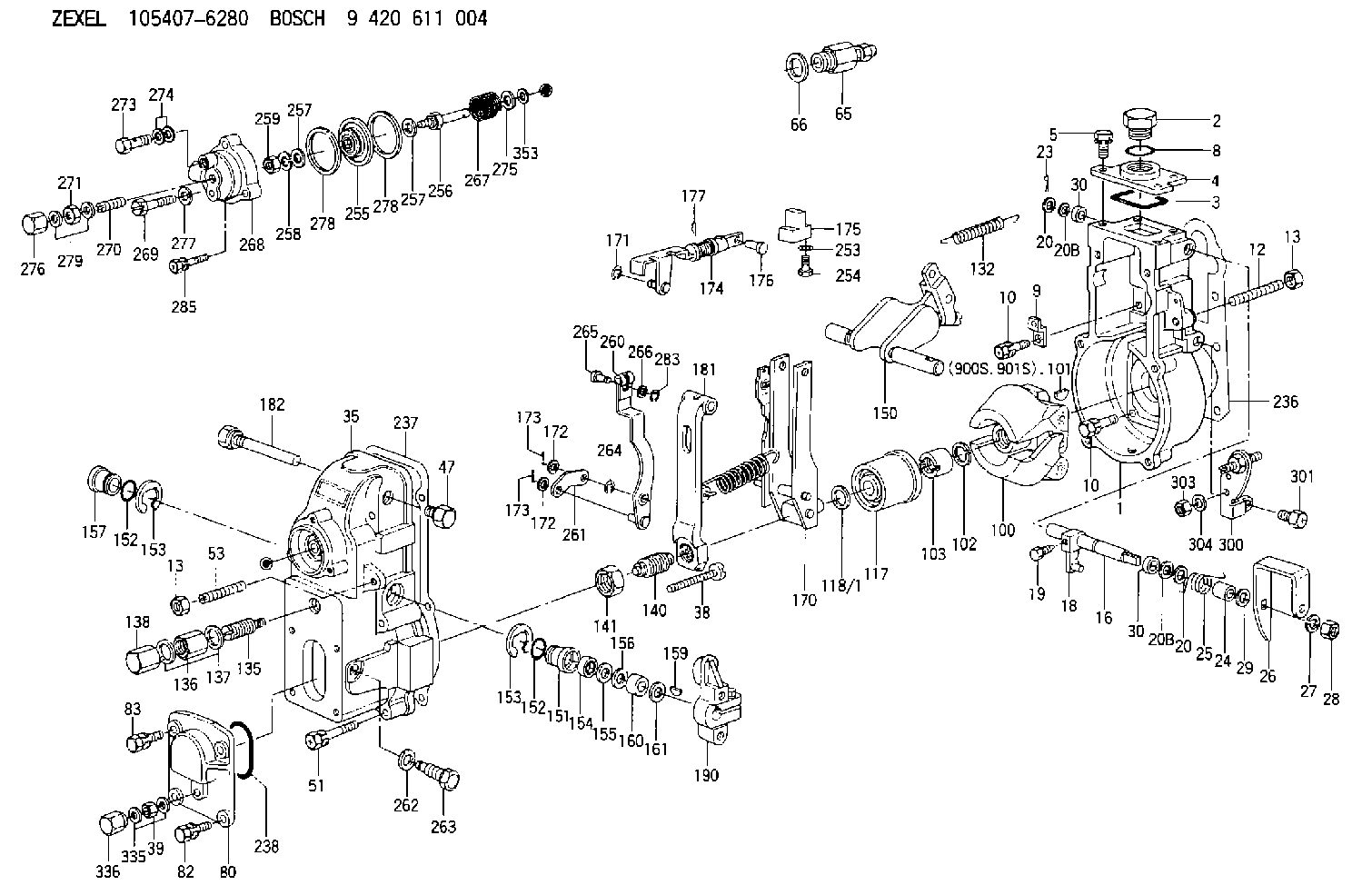
9 420 611 004
9420611004
ZEXEL
105407-6280
1054076280
MITSUBISHI
ME741690
me741690
Rating:
Scheme ###:
| 1. | [1] | 154004-2822 | GOVERNOR HOUSING |
| 2. | [1] | 154007-2900 | CAPSULE |
| 3. | [1] | 154358-2500 | SEAL RING |
| 4. | [1] | 154064-4500 | COVER |
| 5. | [4] | 020006-1640 | BLEEDER SCREW M6P1L16 4T |
| 8. | [1] | 029632-5070 | O-RING |
| 9. | [1] | 154350-6000 | PLATE |
| 10. | [8] | 020106-2040 | BLEEDER SCREW M6P1L20 |
| 10. | [8] | 020106-2040 | BLEEDER SCREW M6P1L20 |
| 12. | [1] | 154010-1100 | FLAT-HEAD SCREW |
| 13. | [2] | 154011-0100 | HEXAGON NUT |
| 13. | [2] | 154011-0100 | HEXAGON NUT |
| 16. | [1] | 155004-3600 | LEVER SHAFT |
| 18. | [1] | 155003-2101 | CONTROL LEVER |
| 19. | [1] | 155006-0700 | BLEEDER SCREW |
| 20. | [1] | 139308-0900 | PLAIN WASHER D16&8T1 |
| 20. | [1] | 139308-0900 | PLAIN WASHER D16&8T1 |
| 20B. | [1] | 139308-1000 | PLAIN WASHER D16&8T1.5 |
| 20B. | [1] | 139308-1000 | PLAIN WASHER D16&8T1.5 |
| 23. | [1] | 025520-1210 | SPLIT PIN |
| 24. | [1] | 154206-2000 | BUSHING |
| 25. | [1] | 154327-4200 | COILED SPRING |
| 26. | [1] | 154381-7900 | CONTROL LEVER |
| 27. | [1] | 014110-8440 | LOCKING WASHER |
| 28. | [1] | 013020-8040 | UNION NUT M8P1.25H7 |
| 29. | [1] | 139408-1500 | SHIM |
| 29B. | [0] | 139408-1400 | SHIM |
| 29C. | [0] | 139408-1500 | SHIM |
| 30. | [2] | 029620-8050 | PACKING RING |
| 30. | [2] | 029620-8050 | PACKING RING |
| 35. | [1] | 154022-7920 | GOVERNOR COVER |
| 38. | [1] | 154031-1300 | FLAT-HEAD SCREW |
| 39. | [1] | 139206-0600 | UNION NUT |
| 47. | [1] | 154036-0300 | CAPSULE |
| 51. | [6] | 020106-5040 | BLEEDER SCREW |
| 53. | [1] | 154010-0200 | FLAT-HEAD SCREW |
| 65. | [1] | 153021-2220 | STOPPING DEVICE |
| 66. | [1] | 026524-3040 | GASKET |
| 80. | [1] | 154063-1400 | COVER |
| 82. | [2] | 029020-6210 | BLEEDER SCREW |
| 83. | [2] | 020006-1640 | BLEEDER SCREW M6P1L16 4T |
| 100. | [1] | 154101-0020 | FLYWEIGHT ASSEMBLY |
| 101. | [1] | 025803-1310 | WOODRUFF KEY |
| 102. | [1] | 029321-2020 | LOCKING WASHER |
| 103. | [1] | 029231-2030 | UNION NUT |
| 117. | [1] | 154123-2320 | SLIDING PIECE |
| 118/1. | [0] | 029311-0010 | SHIM D14&10.1T0.2 |
| 118/1. | [0] | 029311-0180 | SHIM D14&10.1T0.3 |
| 118/1. | [0] | 029311-0190 | SHIM D14&10.1T0.40 |
| 118/1. | [0] | 029311-0210 | SHIM D14&10.1T1 |
| 118/1. | [0] | 139410-0000 | SHIM D14.0&10.1T0.5 |
| 118/1. | [0] | 139410-0100 | SHIM D14.0&10.1T1.5 |
| 118/1. | [0] | 139410-3000 | SHIM D14&10.1T2.0 |
| 118/1. | [0] | 139410-3100 | SHIM D14&10.1T3.0 |
| 118/1. | [0] | 139410-3200 | SHIM D14&10.1T4.0 |
| 132. | [1] | 154154-0500 | COILED SPRING |
| 135. | [1] | 154158-0820 | HEADLESS SCREW |
| 136. | [1] | 029201-2290 | UNION NUT |
| 137. | [2] | 026512-1540 | GASKET D15.4&12.2T1.50 |
| 138. | [1] | 154159-1200 | CAP NUT |
| 140. | [1] | 154177-4320 | HEADLESS SCREW |
| 141. | [1] | 029201-6010 | UNION NUT |
| 150. | [1] | 154200-6920 | SWIVELLING LEVER |
| 151. | [1] | 154204-4300 | BUSHING |
| 152. | [2] | 029631-8020 | O-RING |
| 152. | [2] | 029631-8020 | O-RING |
| 153. | [2] | 016010-1640 | LOCKING WASHER |
| 153. | [2] | 016010-1640 | LOCKING WASHER |
| 154. | [1] | 139611-0000 | PACKING RING |
| 155. | [1] | 139411-0000 | SHIM |
| 156. | [0] | 029311-1070 | SHIM D16&11T0.5 |
| 157. | [1] | 154204-4400 | BUSHING |
| 159. | [1] | 025803-1310 | WOODRUFF KEY |
| 160. | [1] | 154206-2800 | BUSHING |
| 161. | [0] | 154206-0200 | PLAIN WASHER D19.5&11.2T1.0 |
| 170. | [1] | 154217-2920 | FORK LEVER |
| 171. | [1] | 016010-0540 | LOCKING WASHER |
| 172. | [3] | 029310-5170 | SHIM D8&5.3T0.5 |
| 172. | [3] | 029310-5170 | SHIM D8&5.3T0.5 |
| 173. | [2] | 025520-1210 | SPLIT PIN |
| 173. | [2] | 025520-1210 | SPLIT PIN |
| 174. | [1] | 154235-5020 | STRAP |
| 175. | [1] | 154232-2420 | CONNECTOR |
| 176. | [1] | 159231-4900 | BEARING PIN |
| 177. | [1] | 155402-3800 | SAFETY PIN |
| 181. | [1] | 154239-3320 | TENSIONING LEVER |
| 182. | [1] | 154237-1100 | BEARING PIN |
| 190. | [1] | 154340-0120 | CONTROL LEVER |
| 236. | [1] | 154371-5600 | GASKET |
| 237. | [1] | 154390-0300 | GASKET |
| 238. | [1] | 029635-2020 | O-RING |
| 253. | [1] | 029320-5020 | LOCKING WASHER |
| 254. | [1] | 010535-1040 | FLAT-HEAD SCREW M5P0.8L10 |
| 255. | [1] | 154400-7420 | DIAPHRAGM |
| 256. | [1] | 154400-4800 | STOP PIN |
| 257. | [2] | 029330-8050 | GASKET |
| 257. | [2] | 029330-8050 | GASKET |
| 258. | [1] | 139308-0700 | LOCKING WASHER |
| 259. | [1] | 013030-6040 | UNION NUT M6P1H3.6 |
| 260. | [1] | 154401-3620 | CONTROL LEVER |
| 261. | [1] | 154401-1320 | STRAP |
| 262. | [1] | 026510-1440 | GASKET D13.9&10.2T1 |
| 263. | [1] | 154401-2100 | BLEEDER SCREW |
| 264. | [1] | 016010-0540 | LOCKING WASHER |
| 265. | [1] | 154222-6200 | BEARING PIN |
| 266. | [1] | 029300-4010 | PLAIN WASHER |
| 267. | [1] | 154416-2300 | COILED SPRING |
| 268. | [1] | 154404-5000 | COVER |
| 269. | [2] | 020106-2540 | BLEEDER SCREW M6P1L25 |
| 270. | [1] | 154034-1900 | FLAT-HEAD SCREW |
| 271. | [1] | 013030-6040 | UNION NUT M6P1H3.6 |
| 273. | [1] | 029731-0180 | EYE BOLT |
| 274. | [2] | 026510-1340 | GASKET D13.4&10.2T1 |
| 275. | [0] | 029312-0180 | SHIM D25.5&20T0.5 |
| 275B. | [0] | 029312-0210 | SHIM D25.5&20T0.2 |
| 276. | [1] | 154035-1900 | CAP NUT |
| 277. | [1] | 014110-6440 | LOCKING WASHER |
| 278. | [2] | 154413-2600 | GASKET |
| 278. | [2] | 154413-2600 | GASKET |
| 279. | [2] | 026506-1040 | GASKET D9.9&6.2T1 |
| 283. | [1] | 016010-0440 | LOCKING WASHER |
| 285. | [1] | 029010-6310 | BLEEDER SCREW |
| 300. | [1] | 154358-9420 | BRACKET |
| 301. | [1] | 020118-1640 | BLEEDER SCREW |
| 303. | [1] | 154011-1100 | UNION NUT |
| 304. | [1] | 029300-8320 | SHIM |
| 335. | [2] | 026506-1040 | GASKET D9.9&6.2T1 |
| 336. | [1] | 154035-1600 | CAP NUT |
| 353. | [3] | 029310-9080 | SHIM D16&9T1.7 |
| 900S. | [1] | 025803-1310 | WOODRUFF KEY |
| 901S. | [1] | 025803-1610 | WOODRUFF KEY |
Cross reference number
Zexel num
Bosch num
Firm num
Name
105407-6280
ME741690 MITSUBISHI
GOVERNOR
K 14JB MECHANICAL GOVERNOR GOV RSV GOV
K 14JB MECHANICAL GOVERNOR GOV RSV GOV
Information:
GENERAL
Specifications
Components parts
Fuel System Component Parts(1) Injection pump(2) Adjustment shim(3) Injection pipe(4) Injection nozzle(5) Return pipe(6) Fuel filter(7) Fuel cutoff solenoidFUEL INJECTION PUMP
Construction
Injection Pump Component Parts(1) Union collar(2) Air vent screw(3) Delivery valve holder(4) Valve spring(5) Holder stopper(6) Housing(7) O-ring(8) Delivery valve(9) Gasket(10) Seat valve(11) Plunger barrel(12) Sleeve(13) Upper seat(14) Plunger spring(15) Plunger(16) Lower seat(17) Adjusting shim(18) Tappet roller(19) Pin(20) Control rack(21) Stop wire bracketInspecting the injection pump while it is mounted on the engine
Never attempt to disassemble the pump unless it is necessary.If the pump is assumed defective, it is recommended to replace the pump assembly. Removal
(1) Disconnect the fuel injection pipes.(2) Remove the tie-rod clip cover.(3) Remove the tie-rod clip and tie-rod.(4) Remove the injection pump assembly.
Removing Injection PumpDisassembly
(1) Remove the stopper plate.(2) Unscrew the delivery holder. Take out the delivery valve and valve spring.(3) Remove the tappet roller and stopper pin.(4) Remove the tappet, plunger spring, etc. CAUTION1. When replacing the plunger barrel, delivery valve, etc., do not loosen the adjusting screw and plate for each cylinder.2. When those parts have been replaced, it is necessary to measure fuel injection quantity by using the pump tester and cam box.3. All parts removed from the pump should be kept classified by cylinders and immersed in clean fuel.Inspection
Inspection of Injection PumpAssembly
(1) Insert the plunger barrel into the housing.(2) Install the delivery valve and valve spring. Temporarily tighten the holder.(3) Insert the control rack.(4) Insert the control pinion. Align the matchmark on the rack with that on the pinion.(5) Install the spring upper seat.(6) Insert the plunger spring.(7) Fit the lower seat to the plunger. Insert the plunger into the barrel side.(8) Depress the tappet roller assembly and install the stopper pin.(9) Tighten the delivery holder. Tightening torque : 3.5 - 3.9 kgm
Direction of Installation of PlungerInstallation
Install the injection pump assembly in the reverse order of removal. CAUTION* When installing the plunger barrel, engage the dowel pin on the housing side with the groove in the barrel.* Position the plunger so that the part-number stamp on its flanges faces the direction opposite to the rack side. (Engage the feed hole with the plunger lead.)* After installation, check for proper injection timing.INJECTION NOZZLE
Construction
Nozzle Holder Ass'y Component Parts(1) Body sub-assembly(2) Shim washer(3) Pressure spring(4) Pin(5) Distance piece(6) Nozzle assembly(7) Retaining nutRemoval
(1) Disconnect the injection pipe and fuel return pipe.(2) Remove the injection nozzle assembly from the cylinder head. CAUTION* Attach an identification-number tag to the removed injection nozzle.* Plug the openings, from which the pipes are disconnected and the nozzle is removed, to prevent intrusion of dust, water, and other foreign particles into the pipes and combustion chamber.Disassembly
If the removed nozzle assembly is assumed defective, disassemble the assembly and repair or replace the faulty parts.(1) Grip the nozzle holder body in a vise. Loosen the retaining nut. Never vise the retaining nut to prevent deformation.(2) Take out the shim washer, pressure spring, distance piece, and nozzle assembly. CAUTION* Scrape off carbon deposit with a wooden spatula. Keep the removed parts immersed