Information governor
BOSCH
9 420 611 102
9420611102
ZEXEL
105407-6091
1054076091
ISUZU
1157708592
1157708592
Rating:
Scheme ###:
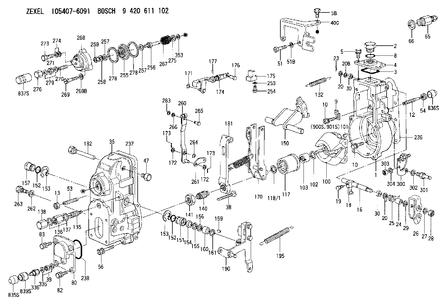
| 1. | [1] | 154004-2822 | GOVERNOR HOUSING |
| 2. | [1] | 154007-2900 | CAPSULE |
| 3. | [1] | 154358-2500 | SEAL RING |
| 4. | [1] | 154064-4500 | COVER |
| 5. | [3] | 020006-1640 | BLEEDER SCREW M6P1L16 4T |
| 5B. | [1] | 020006-2040 | BLEEDER SCREW M6P1L20 4T |
| 8. | [1] | 029632-5070 | O-RING |
| 9. | [1] | 154350-6000 | PLATE |
| 10. | [8] | 020106-2040 | BLEEDER SCREW M6P1L20 |
| 10. | [8] | 020106-2040 | BLEEDER SCREW M6P1L20 |
| 12. | [1] | 154013-5000 | FLAT-HEAD SCREW |
| 13. | [1] | 154011-0100 | HEXAGON NUT |
| 16. | [1] | 155004-3600 | LEVER SHAFT |
| 18. | [1] | 155003-2101 | CONTROL LEVER |
| 19. | [1] | 155006-0700 | BLEEDER SCREW |
| 20. | [1] | 139308-0900 | PLAIN WASHER D16&8T1 |
| 20. | [1] | 139308-0900 | PLAIN WASHER D16&8T1 |
| 20B. | [1] | 139308-1000 | PLAIN WASHER D16&8T1.5 |
| 23. | [1] | 025520-1210 | SPLIT PIN |
| 24. | [1] | 154206-2000 | BUSHING |
| 25. | [1] | 154327-4200 | COILED SPRING |
| 26. | [1] | 154382-3900 | CONTROL LEVER |
| 27. | [1] | 014110-8440 | LOCKING WASHER |
| 28. | [1] | 013020-8040 | UNION NUT M8P1.25H7 |
| 29. | [1] | 139408-1500 | SHIM |
| 29B. | [0] | 139408-1400 | SHIM |
| 29C. | [0] | 139408-1500 | SHIM |
| 30. | [2] | 029620-8050 | PACKING RING |
| 30. | [2] | 029620-8050 | PACKING RING |
| 35. | [1] | 154022-6020 | GOVERNOR COVER |
| 38. | [1] | 154031-4800 | FLAT-HEAD SCREW |
| 39. | [1] | 139208-0400 | UNION NUT |
| 47. | [1] | 154036-0300 | CAPSULE |
| 51. | [2] | 029010-6850 | BLEEDER SCREW |
| 51B. | [2] | 014110-6440 | LOCKING WASHER |
| 53. | [1] | 154010-0200 | FLAT-HEAD SCREW |
| 54. | [1] | 154011-4900 | UNION NUT |
| 56. | [4] | 020106-5040 | BLEEDER SCREW |
| 65. | [1] | 153021-3020 | STOPPING DEVICE |
| 66. | [1] | 026524-3040 | GASKET |
| 80. | [1] | 154063-7300 | COVER |
| 82. | [2] | 029020-6210 | BLEEDER SCREW |
| 83. | [2] | 020006-1640 | BLEEDER SCREW M6P1L16 4T |
| 100. | [1] | 154101-0020 | FLYWEIGHT ASSEMBLY |
| 101. | [1] | 025803-1310 | WOODRUFF KEY |
| 102. | [1] | 029321-2020 | LOCKING WASHER |
| 103. | [1] | 029231-2030 | UNION NUT |
| 117. | [1] | 154123-2320 | SLIDING PIECE |
| 118/1. | [0] | 029311-0010 | SHIM D14&10.1T0.2 |
| 118/1. | [0] | 029311-0180 | SHIM D14&10.1T0.3 |
| 118/1. | [0] | 029311-0190 | SHIM D14&10.1T0.40 |
| 118/1. | [0] | 029311-0210 | SHIM D14&10.1T1 |
| 118/1. | [0] | 139410-0000 | SHIM D14.0&10.1T0.5 |
| 118/1. | [0] | 139410-0100 | SHIM D14.0&10.1T1.5 |
| 118/1. | [0] | 139410-3000 | SHIM D14&10.1T2.0 |
| 118/1. | [0] | 139410-3100 | SHIM D14&10.1T3.0 |
| 118/1. | [0] | 139410-3200 | SHIM D14&10.1T4.0 |
| 132. | [1] | 154154-0500 | COILED SPRING |
| 135. | [1] | 154158-1820 | HEADLESS SCREW |
| 136. | [1] | 029201-2290 | UNION NUT |
| 137. | [2] | 026512-1540 | GASKET D15.4&12.2T1.50 |
| 138. | [1] | 154159-1200 | CAP NUT |
| 140. | [1] | 154185-3620 | HEADLESS SCREW |
| 141. | [1] | 029201-6010 | UNION NUT |
| 150. | [1] | 154200-7220 | SWIVELLING LEVER |
| 151. | [1] | 154204-4300 | BUSHING |
| 152. | [2] | 029631-8020 | O-RING |
| 152. | [2] | 029631-8020 | O-RING |
| 153. | [2] | 016010-1640 | LOCKING WASHER |
| 153. | [2] | 016010-1640 | LOCKING WASHER |
| 154. | [1] | 139611-0000 | PACKING RING |
| 155. | [1] | 139411-0000 | SHIM |
| 156. | [0] | 029311-1070 | SHIM D16&11T0.5 |
| 157. | [1] | 154204-4400 | BUSHING |
| 159. | [1] | 025803-1310 | WOODRUFF KEY |
| 160. | [1] | 154206-2800 | BUSHING |
| 161. | [0] | 154206-0200 | PLAIN WASHER D19.5&11.2T1.0 |
| 170. | [1] | 154217-2920 | FORK LEVER |
| 171. | [1] | 016010-0540 | LOCKING WASHER |
| 172. | [3] | 029310-5170 | SHIM D8&5.3T0.5 |
| 172. | [3] | 029310-5170 | SHIM D8&5.3T0.5 |
| 173. | [3] | 025520-1210 | SPLIT PIN |
| 173. | [3] | 025520-1210 | SPLIT PIN |
| 174. | [1] | 154235-5020 | STRAP |
| 175. | [1] | 154232-2420 | CONNECTOR |
| 176. | [1] | 159231-4900 | BEARING PIN |
| 177. | [1] | 155402-3800 | SAFETY PIN |
| 181. | [1] | 154236-9121 | TENSIONING LEVER |
| 182. | [1] | 154237-1100 | BEARING PIN |
| 190. | [1] | 154303-5220 | CONTROL LEVER |
| 195. | [1] | 154314-0200 | COILED SPRING |
| 236. | [1] | 154371-5600 | GASKET |
| 237. | [1] | 154390-0300 | GASKET |
| 238. | [1] | 029635-2020 | O-RING |
| 253. | [1] | 029320-5020 | LOCKING WASHER |
| 254. | [1] | 010535-1040 | FLAT-HEAD SCREW M5P0.8L10 |
| 255. | [1] | 154400-7420 | DIAPHRAGM |
| 256. | [1] | 154400-4800 | STOP PIN |
| 257. | [2] | 029330-8050 | GASKET |
| 257. | [2] | 029330-8050 | GASKET |
| 258. | [1] | 139308-0700 | LOCKING WASHER |
| 259. | [1] | 013030-6040 | UNION NUT M6P1H3.6 |
| 260. | [1] | 154401-3620 | CONTROL LEVER |
| 261. | [1] | 154401-1320 | STRAP |
| 262. | [1] | 026510-1440 | GASKET D13.9&10.2T1 |
| 263. | [1] | 154401-2100 | BLEEDER SCREW |
| 264. | [1] | 016010-0540 | LOCKING WASHER |
| 265. | [1] | 154222-6200 | BEARING PIN |
| 266. | [1] | 029300-4010 | PLAIN WASHER |
| 267. | [1] | 154416-8400 | COILED SPRING |
| 268. | [1] | 154404-5600 | COVER |
| 269. | [3] | 154062-2900 | BLEEDER SCREW |
| 269B. | [3] | 014110-6440 | LOCKING WASHER |
| 270. | [1] | 154034-1900 | FLAT-HEAD SCREW |
| 271. | [1] | 013030-6040 | UNION NUT M6P1H3.6 |
| 273. | [1] | 029731-0180 | EYE BOLT |
| 274. | [2] | 026510-1340 | GASKET D13.4&10.2T1 |
| 275. | [0] | 029312-0180 | SHIM D25.5&20T0.5 |
| 275B. | [0] | 029312-0210 | SHIM D25.5&20T0.2 |
| 276. | [1] | 154035-1600 | CAP NUT |
| 278. | [2] | 154413-2600 | GASKET |
| 278. | [2] | 154413-2600 | GASKET |
| 279. | [2] | 026506-1040 | GASKET D9.9&6.2T1 |
| 283. | [1] | 016010-0440 | LOCKING WASHER |
| 300. | [1] | 154358-9420 | BRACKET |
| 301. | [1] | 154012-3900 | BLEEDER SCREW |
| 302. | [1] | 014110-8440 | LOCKING WASHER |
| 303. | [1] | 154011-1100 | UNION NUT |
| 304. | [1] | 029300-8320 | SHIM |
| 335. | [2] | 026508-1140 | GASKET D11.4&8.2T1 |
| 336. | [1] | 154035-2900 | CAP NUT |
| 353. | [4] | 029310-9080 | SHIM D16&9T1.7 |
| 400. | [1] | 154375-8220 | BRACKET |
| 835S. | [1] | 154062-4020 | CAP |
| 836S. | [1] | 154062-3520 | CAP |
| 837S. | [1] | 154062-2720 | CAP |
| 839S. | [1] | 154062-3900 | ADAPTOR |
| 900S. | [1] | 025803-1310 | WOODRUFF KEY |
| 901S. | [1] | 025803-1610 | WOODRUFF KEY |
Include in #1:
106671-6061
as GOVERNOR
Cross reference number
Zexel num
Bosch num
Firm num
Name
105407-6091
1157708592 ISUZU
GOVERNOR
K 14JB MECHANICAL GOVERNOR GOV RSV GOV
K 14JB MECHANICAL GOVERNOR GOV RSV GOV
105407-6091
1157708591 ISUZU
GOVERNOR
A K 14JB MECHANICAL GOVERNOR GOV RSV GOV
A K 14JB MECHANICAL GOVERNOR GOV RSV GOV
Information:
Fuel Injection Nozzles
Disassembly of Fuel Injection Nozzles
Inspection of Fuel Injection Nozzles
Check each fuel injection nozzle for the following, and if defects are found, repair or replace the fuel injection nozzle.(1) Inspection of injection start pressure(a) Install each fuel injection nozzle on the nozzle tester, and move the handle up and down to release air.(b) Operate the handle of the tester at a rate of about 1 stroke per second, and read the indication on the pressure gage. The indication rises slowly, and the indicator oscillates during spraying. To obtain the injection start pressure value, read the indication when the indicator starts to oscillate.
Inspection of fuel injection nozzle valve opening(c) If the injection start pressure deviates significantly from the standard value, disassemble the fuel injection nozzle, and make an adjustment by changing the washer thickness. 0.1 mm [0.0039 in.] thickness of shims will change the injection pressure 0.98 Mpa (10 kgf/cm2 [142 psi]. The shims are available in 10 different thickness from 1.25 to 1.70 mm [0.0492 to 0.0669 in.] increment of 0.05 mm [0.0020 in.]
Never tap the tip of the nozzle tip when removing the nozzle tip.
Replacement of fuel injection nozzle tip(2) Inspection of fuel injection nozzle spray pattern(a) When inspecting each fuel injection nozzle with the nozzle tester, also check the nozzle for clogs, spray pattern and leakage.(b) Make sure that the fuel is sprayed straight from the nozzle when the handle of the tester is operated at a rate of about 1 stroke per second.
Inspection of spray pattern of fuel injection nozzle(3) Cleaning and replacement of faulty nozzles(a) Loosen the nozzle retaining nut, remove the nozzle tip, and clean the needle valve and body.
Never tap the tip of the nozzle tip when removing the nozzle tip.
(b) Use a fresh cleaning solution to clean the needle valve and body. After cleaning, assemble the needle valve and body in clean diesel fuel. The needle valve and body are precision finished. Handle them carefully, and do not change the combination of parts.
Cleaning of fuel injection nozzle tip(c) Tighten the nozzle retaining nut on the nozzle tip to the specified torque.(d) If the spray pattern is still not acceptable after adjustment and cleaning, replace the nozzle tip. (a) Never touch the sliding surface of the needle valve.(b) When installing a new nozzle tip, remove the seal film (synthetic resin film), and slide needle valve in the nozzle in a fresh cleaning solution to remove anti-rust oil coating thoroughly from the new nozzleReassembly of Fuel Injection Nozzles
Fuel Filter
Disassembly and Inspection of Fuel Filter