Information governor
BOSCH
9 420 611 672
9420611672
ZEXEL
105407-5991
1054075991
MITSUBISHI
ME742712
me742712
Rating:
Scheme ###:
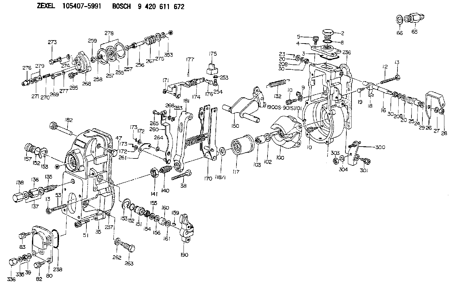
| 1. | [1] | 154004-2822 | GOVERNOR HOUSING |
| 2. | [1] | 154007-2900 | CAPSULE |
| 3. | [1] | 154358-2500 | SEAL RING |
| 4. | [1] | 154063-7900 | COVER |
| 5. | [4] | 020006-1640 | BLEEDER SCREW M6P1L16 4T |
| 8. | [1] | 029632-5070 | O-RING |
| 9. | [1] | 154350-6000 | PLATE |
| 10. | [8] | 020106-2040 | BLEEDER SCREW M6P1L20 |
| 10. | [8] | 020106-2040 | BLEEDER SCREW M6P1L20 |
| 12. | [1] | 154010-1100 | FLAT-HEAD SCREW |
| 13. | [2] | 154011-0100 | HEXAGON NUT |
| 13. | [2] | 154011-0100 | HEXAGON NUT |
| 16. | [1] | 155004-3600 | LEVER SHAFT |
| 18. | [1] | 155003-2101 | CONTROL LEVER |
| 19. | [1] | 155006-0700 | BLEEDER SCREW |
| 20. | [1] | 139308-0900 | PLAIN WASHER D16&8T1 |
| 20. | [1] | 139308-0900 | PLAIN WASHER D16&8T1 |
| 20B. | [1] | 139308-1000 | PLAIN WASHER D16&8T1.5 |
| 20B. | [1] | 139308-1000 | PLAIN WASHER D16&8T1.5 |
| 23. | [1] | 025520-1210 | SPLIT PIN |
| 24. | [1] | 154206-2000 | BUSHING |
| 25. | [1] | 154327-4200 | COILED SPRING |
| 26. | [1] | 154381-7900 | CONTROL LEVER |
| 27. | [1] | 014110-8440 | LOCKING WASHER |
| 28. | [1] | 013020-8040 | UNION NUT M8P1.25H7 |
| 29. | [1] | 139408-1500 | SHIM |
| 29B. | [0] | 139408-1400 | SHIM |
| 29C. | [0] | 139408-1500 | SHIM |
| 30. | [2] | 029620-8050 | PACKING RING |
| 30. | [2] | 029620-8050 | PACKING RING |
| 35. | [1] | 154022-7920 | GOVERNOR COVER |
| 38. | [1] | 154031-1300 | FLAT-HEAD SCREW |
| 39. | [1] | 139206-0600 | UNION NUT |
| 47. | [1] | 154036-0300 | CAPSULE |
| 51. | [6] | 020106-5040 | BLEEDER SCREW |
| 53. | [1] | 154010-0100 | FLAT-HEAD SCREW |
| 65. | [1] | 153021-2220 | STOPPING DEVICE |
| 66. | [1] | 026524-3040 | GASKET |
| 80. | [1] | 154063-1400 | COVER |
| 82. | [2] | 029020-6210 | BLEEDER SCREW |
| 83. | [2] | 020006-1640 | BLEEDER SCREW M6P1L16 4T |
| 100. | [1] | 154101-0020 | FLYWEIGHT ASSEMBLY |
| 101. | [1] | 025803-1310 | WOODRUFF KEY |
| 102. | [1] | 029321-2020 | LOCKING WASHER |
| 103. | [1] | 029231-2030 | UNION NUT |
| 117. | [1] | 154123-2320 | SLIDING PIECE |
| 118/1. | [0] | 029311-0010 | SHIM D14&10.1T0.2 |
| 118/1. | [0] | 029311-0180 | SHIM D14&10.1T0.3 |
| 118/1. | [0] | 029311-0190 | SHIM D14&10.1T0.40 |
| 118/1. | [0] | 029311-0210 | SHIM D14&10.1T1 |
| 118/1. | [0] | 139410-0000 | SHIM D14.0&10.1T0.5 |
| 118/1. | [0] | 139410-0100 | SHIM D14.0&10.1T1.5 |
| 118/1. | [0] | 139410-3000 | SHIM D14&10.1T2.0 |
| 118/1. | [0] | 139410-3100 | SHIM D14&10.1T3.0 |
| 118/1. | [0] | 139410-3200 | SHIM D14&10.1T4.0 |
| 132. | [1] | 154154-0500 | COILED SPRING |
| 135. | [1] | 154158-1820 | HEADLESS SCREW |
| 136. | [1] | 029201-2290 | UNION NUT |
| 137. | [2] | 026512-1540 | GASKET D15.4&12.2T1.50 |
| 138. | [1] | 154159-1200 | CAP NUT |
| 140. | [1] | 154185-2120 | HEADLESS SCREW |
| 141. | [1] | 029201-6010 | UNION NUT |
| 150. | [1] | 154200-6920 | SWIVELLING LEVER |
| 151. | [1] | 154204-3000 | BUSHING |
| 152. | [2] | 029631-8020 | O-RING |
| 152. | [2] | 029631-8020 | O-RING |
| 153. | [2] | 016010-1640 | LOCKING WASHER |
| 153. | [2] | 016010-1640 | LOCKING WASHER |
| 154. | [1] | 139611-0000 | PACKING RING |
| 155. | [1] | 139411-0000 | SHIM |
| 156. | [0] | 029311-1070 | SHIM D16&11T0.5 |
| 157. | [1] | 154204-3100 | BUSHING |
| 159. | [1] | 025803-1310 | WOODRUFF KEY |
| 160. | [1] | 154206-2800 | BUSHING |
| 161. | [0] | 154206-0200 | PLAIN WASHER D19.5&11.2T1.0 |
| 170. | [1] | 154217-2920 | FORK LEVER |
| 171. | [1] | 016010-0540 | LOCKING WASHER |
| 172. | [4] | 029310-5170 | SHIM D8&5.3T0.5 |
| 172. | [4] | 029310-5170 | SHIM D8&5.3T0.5 |
| 173. | [3] | 025520-1210 | SPLIT PIN |
| 173. | [3] | 025520-1210 | SPLIT PIN |
| 174. | [1] | 154234-6920 | STRAP |
| 175. | [1] | 154232-2420 | CONNECTOR |
| 176. | [1] | 159231-4900 | BEARING PIN |
| 177. | [1] | 155402-3800 | SAFETY PIN |
| 181. | [1] | 154239-3320 | TENSIONING LEVER |
| 182. | [1] | 154237-1100 | BEARING PIN |
| 190. | [1] | 154340-0120 | CONTROL LEVER |
| 236. | [1] | 154371-5600 | GASKET |
| 237. | [1] | 154390-0300 | GASKET |
| 238. | [1] | 029635-2020 | O-RING |
| 253. | [1] | 029320-5020 | LOCKING WASHER |
| 254. | [1] | 010535-1040 | FLAT-HEAD SCREW M5P0.8L10 |
| 255. | [1] | 154400-7420 | DIAPHRAGM |
| 256. | [1] | 154400-4800 | STOP PIN |
| 257. | [2] | 029330-8050 | GASKET |
| 257. | [2] | 029330-8050 | GASKET |
| 258. | [1] | 139308-0700 | LOCKING WASHER |
| 259. | [1] | 013030-6040 | UNION NUT M6P1H3.6 |
| 260. | [1] | 154401-3620 | CONTROL LEVER |
| 261. | [1] | 154401-1320 | STRAP |
| 262. | [1] | 026510-1440 | GASKET D13.9&10.2T1 |
| 263. | [1] | 154401-2100 | BLEEDER SCREW |
| 264. | [1] | 016010-0540 | LOCKING WASHER |
| 265. | [1] | 154222-6200 | BEARING PIN |
| 266. | [1] | 029300-4010 | PLAIN WASHER |
| 267. | [1] | 154403-0900 | COILED SPRING |
| 268. | [1] | 154404-5000 | COVER |
| 269. | [2] | 020106-2540 | BLEEDER SCREW M6P1L25 |
| 270. | [1] | 154034-1900 | FLAT-HEAD SCREW |
| 271. | [1] | 013030-6040 | UNION NUT M6P1H3.6 |
| 273. | [1] | 029731-0180 | EYE BOLT |
| 274. | [2] | 026510-1340 | GASKET D13.4&10.2T1 |
| 275. | [0] | 029312-0180 | SHIM D25.5&20T0.5 |
| 275B. | [0] | 029312-0210 | SHIM D25.5&20T0.2 |
| 276. | [1] | 154035-1900 | CAP NUT |
| 277. | [1] | 014110-6440 | LOCKING WASHER |
| 278. | [2] | 154413-2600 | GASKET |
| 279. | [2] | 026506-1040 | GASKET D9.9&6.2T1 |
| 283. | [1] | 016010-0440 | LOCKING WASHER |
| 285. | [1] | 029010-6310 | BLEEDER SCREW |
| 300. | [1] | 154358-9420 | BRACKET |
| 301. | [1] | 020118-1640 | BLEEDER SCREW |
| 303. | [1] | 154011-1100 | UNION NUT |
| 304. | [1] | 029300-8320 | SHIM |
| 335. | [2] | 026506-1040 | GASKET D9.9&6.2T1 |
| 336. | [1] | 154035-1600 | CAP NUT |
| 353. | [2] | 029310-9080 | SHIM D16&9T1.7 |
| 900S. | [1] | 025803-1310 | WOODRUFF KEY |
| 901S. | [1] | 025803-1610 | WOODRUFF KEY |
Include in #1:
106673-7192
as GOVERNOR
Cross reference number
Zexel num
Bosch num
Firm num
Name
105407-5991
ME742712 MITSUBISHI
GOVERNOR
K 14JB MECHANICAL GOVERNOR GOV RSV GOV
K 14JB MECHANICAL GOVERNOR GOV RSV GOV
Information:
In this service manual, the Mitsubishi Diesel Engine (standard model for land use) specifications, maintenance standards and adjustment procedure as well as service procedures such as disassembly, inspection, repair and reassembly are arranged in groups for quick reference. There are separate manuals for the fuel injection pump, governor and turbocharger.A short summary of each group is given in the General Contents, and there is also a table of contents at the beginning of each group.Regarding engine operation and periodical maintenance, refer to the Operation & Maintenance Manual. For component parts and ordering of service parts, refer to the Parts Catalog. Structure and function of the engine are described in various training manuals.Methods of Indication
(1) Parts shown in illustrations and described in text are numbered to correspond with the sequence of disassembly.(2) Inspections to be conducted during disassembly are indicated in a box
in disassembled views.(3) Maintenance standards for inspection and repair are described in text where they are relevant, are also listed in Group 1 in the General Contents.(4) The sequence in which parts are to be assembled is summarized below each assembled view. Such as:
(5) The following marks are used in this manual to emphasize important safety cautions.
Indicates a highly hazardous situation which, if not avoided, can result in death or serious injury.
Indicates a potentially hazardous situation which, if not avoided, can result in death or serious injury.
Indicates a potentially hazardous situation which, if not avoided, can result in minor or moderate injury.
Indicates a potentially hazardous situation which, if not avoided, can result in property damage. Note: Indicates important information or information which is useful for engine operation or maintenance.(6) Tightening torque under wet conditions is indicated as, "[Wet]". When so indicated, apply engine oil to the threaded portion of the fastener. Unless indicated as such, the tightening torque is to be assumed in the dry condition.Terms Used in This Manual
Nominal value - Indicates the standard dimension of a part to be measured.Standard - Indicates the dimension of a part, the clearance between parts, or the standard performance. Since the value is indicated in a range needed for inspection, it is different from the design value.Limit - A part must be repaired or replaced with a new part when it reaches the limit value.Abbreviations, Standard, Etc.
* BTDC = Before Top Dead Center* ATDC = After Top Dead Center* BBDC = Before Bottom Dead Center* ABDC = After Bottom Dead Center* TIR = Total Indicated Reading* API = American Petroleum Institute* ASTM = American Society for Testing and Materials* JIS = Japanese Industrial Standards* LLC = Long Life Coolant* MIL = Military Specifications and Standards (U.S.)* MSDS = Material Safety Data Sheet* SAE = Society of Automotive Engineers (U.S.)Units of Measurement
Measurements are based on the International System of Units (SI), and their converted metric values are indicated in parentheses ( ). For metric conversion, the following rates are used.* Pressure: 1 MPa = 10.197 kgf/cm2* Torque: 1 N m = 0.10197 kgf m* Force: 1 N