Information governor
BOSCH
F 019 Z3E 875
f019z3e875
ZEXEL
105407-5923
1054075923
HINO
223204940B
223204940b
Rating:
Scheme ###:
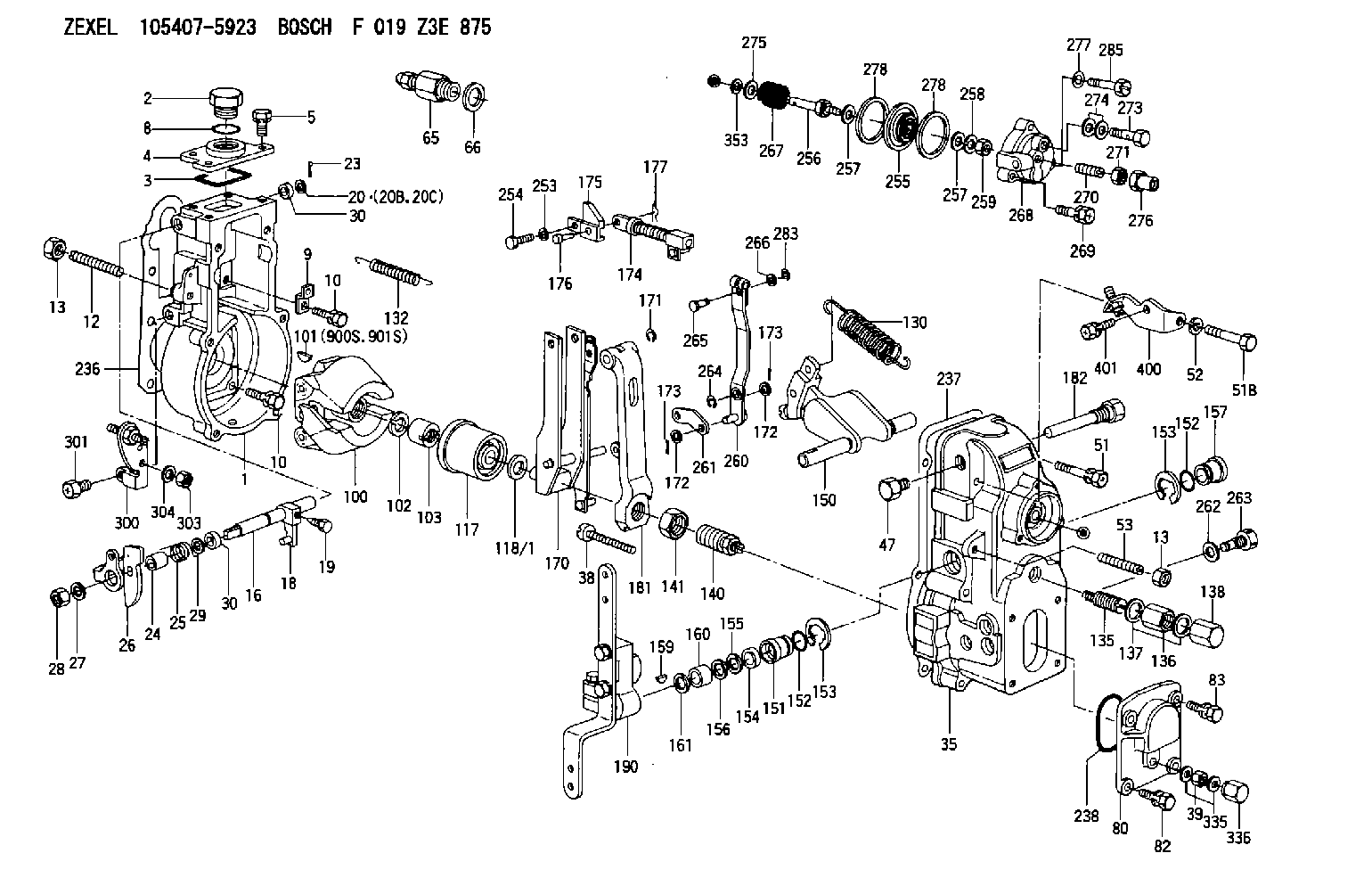
| 1. | [1] | 154004-2822 | GOVERNOR HOUSING |
| 2. | [1] | 154007-2900 | CAPSULE |
| 3. | [1] | 154358-2500 | SEAL RING |
| 4. | [1] | 154064-4500 | COVER |
| 5. | [4] | 020006-1640 | BLEEDER SCREW M6P1L16 4T |
| 8. | [1] | 029632-5070 | O-RING |
| 9. | [1] | 154350-6000 | PLATE |
| 10. | [8] | 020106-2040 | BLEEDER SCREW M6P1L20 |
| 10. | [8] | 020106-2040 | BLEEDER SCREW M6P1L20 |
| 12. | [1] | 154010-1100 | FLAT-HEAD SCREW |
| 13. | [2] | 154011-0100 | HEXAGON NUT |
| 13. | [2] | 154011-0100 | HEXAGON NUT |
| 16. | [1] | 155004-3600 | LEVER SHAFT |
| 18. | [1] | 155003-2101 | CONTROL LEVER |
| 19. | [1] | 155006-0700 | BLEEDER SCREW |
| 20. | [1] | 139308-0900 | PLAIN WASHER D16&8T1 |
| 20B. | [1] | 139308-1000 | PLAIN WASHER D16&8T1.5 |
| 23. | [1] | 025520-1210 | SPLIT PIN |
| 24. | [1] | 154206-2000 | BUSHING |
| 25. | [1] | 154327-4200 | COILED SPRING |
| 26. | [1] | 154382-6200 | CONTROL LEVER |
| 27. | [1] | 014110-8440 | LOCKING WASHER |
| 28. | [1] | 013020-8040 | UNION NUT M8P1.25H7 |
| 29. | [1] | 139408-1500 | SHIM |
| 29B. | [0] | 139408-1400 | SHIM |
| 29C. | [0] | 139408-1500 | SHIM |
| 30. | [2] | 029620-8050 | PACKING RING |
| 30. | [2] | 029620-8050 | PACKING RING |
| 35. | [1] | 154022-6020 | GOVERNOR COVER |
| 38. | [1] | 154031-4800 | FLAT-HEAD SCREW |
| 39. | [1] | 139208-0400 | UNION NUT |
| 47. | [1] | 154036-1200 | CAPSULE |
| 51. | [5] | 020106-5040 | BLEEDER SCREW |
| 51B. | [1] | 029010-6850 | BLEEDER SCREW |
| 52. | [1] | 014110-6440 | LOCKING WASHER |
| 53. | [1] | 154010-0100 | FLAT-HEAD SCREW |
| 65. | [1] | 153021-2220 | STOPPING DEVICE |
| 66. | [1] | 026524-3040 | GASKET |
| 80. | [1] | 154063-7300 | COVER |
| 82. | [2] | 029020-6210 | BLEEDER SCREW |
| 83. | [2] | 020006-1640 | BLEEDER SCREW M6P1L16 4T |
| 100. | [1] | 154101-0020 | FLYWEIGHT ASSEMBLY |
| 101. | [1] | 025803-1310 | WOODRUFF KEY |
| 102. | [1] | 029321-2020 | LOCKING WASHER |
| 103. | [1] | 029231-2030 | UNION NUT |
| 117. | [1] | 154123-2320 | SLIDING PIECE |
| 118/1. | [0] | 029311-0010 | SHIM D14&10.1T0.2 |
| 118/1. | [0] | 029311-0180 | SHIM D14&10.1T0.3 |
| 118/1. | [0] | 029311-0190 | SHIM D14&10.1T0.40 |
| 118/1. | [0] | 029311-0210 | SHIM D14&10.1T1 |
| 118/1. | [0] | 139410-0000 | SHIM D14.0&10.1T0.5 |
| 118/1. | [0] | 139410-0100 | SHIM D14.0&10.1T1.5 |
| 118/1. | [0] | 139410-3000 | SHIM D14&10.1T2.0 |
| 118/1. | [0] | 139410-3100 | SHIM D14&10.1T3.0 |
| 118/1. | [0] | 139410-3200 | SHIM D14&10.1T4.0 |
| 130. | [1] | 154150-2900 | GOVERNOR SPRING |
| 132. | [1] | 154154-0500 | COILED SPRING |
| 135. | [1] | 154158-0820 | HEADLESS SCREW |
| 136. | [1] | 029201-2290 | UNION NUT |
| 137. | [2] | 026512-1540 | GASKET D15.4&12.2T1.50 |
| 138. | [1] | 154159-1200 | CAP NUT |
| 140. | [1] | 154185-1320 | HEADLESS SCREW |
| 141. | [1] | 029201-6010 | UNION NUT |
| 150. | [1] | 154200-7020 | SWIVELLING LEVER |
| 151. | [1] | 154204-4300 | BUSHING |
| 152. | [2] | 029631-8020 | O-RING |
| 152. | [2] | 029631-8020 | O-RING |
| 153. | [2] | 016010-1640 | LOCKING WASHER |
| 153. | [2] | 016010-1640 | LOCKING WASHER |
| 154. | [1] | 139611-0000 | PACKING RING |
| 155. | [1] | 139411-0000 | SHIM |
| 156. | [0] | 029311-1070 | SHIM D16&11T0.5 |
| 157. | [1] | 154204-4400 | BUSHING |
| 159. | [1] | 025803-1310 | WOODRUFF KEY |
| 160. | [1] | 154206-2800 | BUSHING |
| 161. | [0] | 154206-0200 | PLAIN WASHER D19.5&11.2T1.0 |
| 170. | [1] | 154217-2920 | FORK LEVER |
| 171. | [1] | 016010-0540 | LOCKING WASHER |
| 172. | [3] | 029310-5170 | SHIM D8&5.3T0.5 |
| 172. | [3] | 029310-5170 | SHIM D8&5.3T0.5 |
| 173. | [2] | 025520-1210 | SPLIT PIN |
| 173. | [2] | 025520-1210 | SPLIT PIN |
| 174. | [1] | 154235-5020 | STRAP |
| 175. | [1] | 154232-2420 | CONNECTOR |
| 176. | [1] | 159231-4900 | BEARING PIN |
| 177. | [1] | 155402-3800 | SAFETY PIN |
| 181. | [1] | 154236-4100 | TENSIONING LEVER |
| 182. | [1] | 154237-1100 | BEARING PIN |
| 190. | [1] | 154341-8120 | CONTROL LEVER |
| 236. | [1] | 154371-5600 | GASKET |
| 237. | [1] | 154390-0300 | GASKET |
| 238. | [1] | 029635-2020 | O-RING |
| 253. | [1] | 029320-5020 | LOCKING WASHER |
| 254. | [1] | 010535-1040 | FLAT-HEAD SCREW M5P0.8L10 |
| 255. | [1] | 154400-7420 | DIAPHRAGM |
| 256. | [1] | 154400-4800 | STOP PIN |
| 257. | [2] | 029330-8050 | GASKET |
| 257. | [2] | 029330-8050 | GASKET |
| 258. | [1] | 139308-0700 | LOCKING WASHER |
| 259. | [1] | 013030-6040 | UNION NUT M6P1H3.6 |
| 260. | [1] | 154401-3620 | CONTROL LEVER |
| 261. | [1] | 154401-1320 | STRAP |
| 262. | [1] | 026510-1440 | GASKET D13.9&10.2T1 |
| 263. | [1] | 154401-2100 | BLEEDER SCREW |
| 264. | [1] | 016010-0540 | LOCKING WASHER |
| 265. | [1] | 154222-6200 | BEARING PIN |
| 266. | [1] | 029300-4010 | PLAIN WASHER |
| 267. | [1] | 154416-1200 | COILED SPRING |
| 268. | [1] | 154404-5000 | COVER |
| 269. | [2] | 020106-2540 | BLEEDER SCREW M6P1L25 |
| 270. | [1] | 154034-1900 | FLAT-HEAD SCREW |
| 271. | [1] | 023040-6040 | UNION NUT |
| 273. | [1] | 029731-0180 | EYE BOLT |
| 274. | [2] | 026510-1340 | GASKET D13.4&10.2T1 |
| 275. | [0] | 029312-0180 | SHIM D25.5&20T0.5 |
| 275B. | [0] | 029312-0210 | SHIM D25.5&20T0.2 |
| 276. | [1] | 154035-0320 | CAP NUT |
| 277. | [1] | 014110-6440 | LOCKING WASHER |
| 278. | [2] | 154413-2600 | GASKET |
| 278. | [2] | 154413-2600 | GASKET |
| 283. | [1] | 016010-0440 | LOCKING WASHER |
| 285. | [1] | 029010-6310 | BLEEDER SCREW |
| 300. | [1] | 154359-1320 | BRACKET |
| 301. | [1] | 020118-1640 | BLEEDER SCREW |
| 303. | [1] | 154011-1100 | UNION NUT |
| 304. | [1] | 029300-8320 | SHIM |
| 335. | [2] | 026508-1140 | GASKET D11.4&8.2T1 |
| 336. | [1] | 154035-2000 | CAP NUT |
| 353. | [1] | 029310-9080 | SHIM D16&9T1.7 |
| 400. | [1] | 154375-8120 | BRACKET |
| 401. | [1] | 020006-1240 | BLEEDER SCREW M6P1L12 4T |
| 900S. | [1] | 025803-1310 | WOODRUFF KEY |
| 901S. | [1] | 025803-1610 | WOODRUFF KEY |
Include in #1:
106671-8794
as GOVERNOR
Cross reference number
Zexel num
Bosch num
Firm num
Name
105407-5923
223204940B HINO
GOVERNOR
K 14JB MECHANICAL GOVERNOR GOV RSV GOV
K 14JB MECHANICAL GOVERNOR GOV RSV GOV
Information:
Installing main bearings(b) Fit the flanged main bearing in the No. 3 journal position.(c) Smear a little engine oil on the inner surface of each bearing.
Installing flanged main bearingInstalling Crankshaft
(a) Wash the crankshaft thoroughly in cleaning solvent, then dry it with compressed air.(b) Keeping the crankshaft horizontal, gently lower it into the cylinder block.(c) Smear a little engine oil on each crankshaft journal.
Installing crankshaftInstalling Main Bearing Caps
(a) Before installing the main bearing caps, apply sealant to the mating surfaces of the frontmost and rearmost caps and to the corresponding surfaces in the cylinder block.
Installing main bearing caps(b) Referring to the cap numbers, fit the main bearing caps sequentially starting at the front of the engine. The arrow on each cap must point toward the front of the engine.
Front marks and cap numbers
Make sure the frontmost and rearmost caps fit flush against the cylinder block.
(4) Tightening Bearing Cap Bolts
Tighten the bearing cap bolts alternately a little at a time, then torque each bolt to specification.
Tightening bearing cap bolts(5) Checking Crankshaft Rotation
Confirm that the crankshaft turns smoothly.
Checking crankshaft rotation(6) Measuring End Plan of Crankshaft
Apply a dial gauge to the end of the crankshaft and measure the end play. If the measurement exceeds the specified limit, replace the No. 3 flanged bearing.
Measuring end play of crankshaft(7) Inserting Side Seals
(a) Apply sealant to the mating surfaces of each side seal. (b) With the radius of each side seal facing the outside, push the side seals part-way into the frontmost and rearmost caps by hand.
Alignment of side seals for installation(c) Press each side seal completely into position using a flat implement. Be careful not to bend the side seals.
Inserting side seals(8) Preparation for Installation of Piston and Connecting Rod Assemblies
(a) Clean each cylinder's inner surface with a rag, then smear each with engine oil.(b) Press the connecting rod bearings (upper and lower) into the connecting rods and caps such that the bearings' lugs fir into the grooves.(c) Smear the connecting rod bearings with engine oil.(d) Turn the cylinder block onto its side.
Preparation for installation of piston and connecting rod assemblies(9) Installing Piston and Connecting Rod Assemblies
(a) Smear the pistons' sliding surfaces and piston rings with engine oil(b) Position the piston ring gaps as shown in the illustration. Do not align any ring gap with the piston pin or at 90° to the piston pin.
Piston ring positions(c) Turn the crankshaft until the crank pin onto which the connecting rod is to be fitted reaches its TDC position.(d) Align the piston such that its front mark (this is stamped on the piston crown) points toward the timing gear case mounting surface (the front of the engine).(e) Using a piston guide (commercially available), insert the piston and connecting rod assembly into the cylinder from the top of the cylinder block.
Inserting piston and connecting rod assembly
If the piston is tapped hard while being inserted, the piston rings may break and the crank pin may become damaged.
(10) Installing Connecting Rod Caps
(a) When the connecting rod's big end is