Information governor
BOSCH
9 420 610 831
9420610831
ZEXEL
105407-5871
1054075871
NISSAN-DIESEL
1910196373
1910196373
Rating:
Scheme ###:
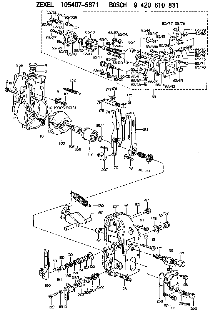
| 1. | [1] | 154000-4700 | GOVERNOR HOUSING |
| 3. | [1] | 029632-5070 | O-RING |
| 4. | [1] | 154007-2900 | CAPSULE |
| 9. | [1] | 154350-6000 | PLATE |
| 10. | [8] | 020106-2040 | BLEEDER SCREW M6P1L20 |
| 10. | [8] | 020106-2040 | BLEEDER SCREW M6P1L20 |
| 12. | [1] | 154010-0100 | FLAT-HEAD SCREW |
| 13. | [2] | 154011-0100 | HEXAGON NUT |
| 13. | [2] | 154011-0100 | HEXAGON NUT |
| 35. | [1] | 154500-1020 | GOVERNOR COVER |
| 35/2. | [1] | 154321-0400 | BUSHING |
| 38. | [1] | 154031-2400 | FLAT-HEAD SCREW |
| 39. | [1] | 139206-0600 | UNION NUT |
| 47. | [2] | 154036-0300 | CAPSULE |
| 47. | [2] | 154036-0300 | CAPSULE |
| 51. | [2] | 020106-5040 | BLEEDER SCREW |
| 53. | [1] | 154010-0100 | FLAT-HEAD SCREW |
| 56. | [4] | 020106-3840 | BLEEDER SCREW |
| 65. | [1] | 154421-7120 | MANIFOLD-PRESSURE COMP. |
| 65/1. | [1] | 154412-9520 | GOVERNOR HOUSING |
| 65/1A. | [1] | 154412-0201 | SPACER BUSHING |
| 65/1B. | [1] | 134009-0000 | SPACER BUSHING |
| 65/4. | [1] | 154413-0500 | BUSHING |
| 65/9. | [1] | 154402-3900 | COILED SPRING |
| 65/10. | [1] | 154400-8220 | DIAPHRAGM |
| 65/11. | [1] | 154412-4101 | STOP PIN |
| 65/14. | [1] | 154406-5500 | SLOTTED WASHER |
| 65/15. | [1] | 013020-6040 | UNION NUT M6P1H5 |
| 65/16. | [1] | 154416-0200 | COILED SPRING |
| 65/17. | [2] | 154413-2600 | GASKET |
| 65/18. | [1] | 154404-5000 | COVER |
| 65/20. | [2] | 029010-6310 | BLEEDER SCREW |
| 65/20B. | [1] | 020106-4540 | BLEEDER SCREW M6P1.0L45 |
| 65/21. | [2] | 014110-6440 | LOCKING WASHER |
| 65/24. | [2] | 020106-2040 | BLEEDER SCREW M6P1L20 |
| 65/27. | [1] | 029731-0180 | EYE BOLT |
| 65/28. | [2] | 026510-1340 | GASKET D13.4&10.2T1 |
| 65/29. | [1] | 154390-2200 | GASKET |
| 65/43. | [1] | 154390-2300 | GASKET |
| 65/45. | [1] | 029331-8040 | GASKET |
| 65/46. | [1] | 154406-5800 | FLAT-HEAD SCREW |
| 65/47. | [1] | 014110-6440 | LOCKING WASHER |
| 65/50. | [1] | 154406-6800 | PLAIN WASHER |
| 65/51. | [1] | 154412-9800 | CONTROL LEVER |
| 65/52. | [1] | 014110-4440 | LOCKING WASHER |
| 65/53. | [1] | 010234-0820 | HEX-SOCKET-HEAD CAP SCREW |
| 65/54. | [1] | 013030-6040 | UNION NUT M6P1H3.6 |
| 65/55. | [1] | 154404-1500 | FLAT-HEAD SCREW L22.00 |
| 65/55B. | [1] | 154404-1600 | FLAT-HEAD SCREW L26.00 |
| 65/56. | [1] | 029331-2130 | GASKET |
| 65/57. | [1] | 154406-6500 | FLAT-HEAD SCREW |
| 65/58. | [2] | 020106-2840 | BLEEDER SCREW |
| 65/58A. | [1] | 020106-1440 | BLEEDER SCREW M6P1.0L14 |
| 65/59. | [1] | 010006-7040 | BLEEDER SCREW M6P1L70 |
| 65/60. | [1] | 014110-6440 | LOCKING WASHER |
| 65/61. | [1] | 154035-1600 | CAP NUT |
| 65/62. | [1] | 154404-4400 | FLAT-HEAD SCREW |
| 65/63. | [1] | 013030-6040 | UNION NUT M6P1H3.6 |
| 65/64. | [2] | 026506-1040 | GASKET D9.9&6.2T1 |
| 65/70. | [1] | 029240-6010 | UNION NUT M6P1.0H5* |
| 65/71. | [1] | 153141-1600 | BLEEDER SCREW |
| 65/72. | [1] | 154413-0021 | LEVER SHAFT |
| 65/73. | [1] | 154413-0100 | BUSHING |
| 65/74. | [1] | 139608-0000 | PACKING RING |
| 65/75. | [1] | 154413-0200 | PLAIN WASHER |
| 65/76. | [0] | 029310-8030 | SHIM D13.5&8T0.1 |
| 65/76B. | [0] | 029310-8040 | SHIM D13.5&8T0.2 |
| 65/77. | [1] | 154413-0301 | COILED SPRING |
| 65/78. | [1] | 154413-0400 | CONTROL LEVER |
| 65/79. | [1] | 014110-8440 | LOCKING WASHER |
| 65/80. | [1] | 013020-8140 | UNION NUT M8P1.25H6.5 |
| 80. | [1] | 154063-1400 | COVER |
| 82. | [2] | 029020-6210 | BLEEDER SCREW |
| 83. | [2] | 020006-1640 | BLEEDER SCREW M6P1L16 4T |
| 100. | [1] | 154100-9720 | FLYWEIGHT ASSEMBLY |
| 101. | [1] | 025803-1310 | WOODRUFF KEY |
| 102. | [1] | 029321-2020 | LOCKING WASHER |
| 103. | [1] | 029231-2030 | UNION NUT |
| 117. | [1] | 154123-0120 | SLIDING PIECE |
| 118/1. | [0] | 029311-0010 | SHIM D14&10.1T0.2 |
| 118/1. | [0] | 029311-0180 | SHIM D14&10.1T0.3 |
| 118/1. | [0] | 029311-0190 | SHIM D14&10.1T0.40 |
| 118/1. | [0] | 029311-0210 | SHIM D14&10.1T1 |
| 118/1. | [0] | 139410-0000 | SHIM D14.0&10.1T0.5 |
| 118/1. | [0] | 139410-0100 | SHIM D14.0&10.1T1.5 |
| 118/1. | [0] | 139410-3000 | SHIM D14&10.1T2.0 |
| 118/1. | [0] | 139410-3100 | SHIM D14&10.1T3.0 |
| 118/1. | [0] | 139410-3200 | SHIM D14&10.1T4.0 |
| 130. | [1] | 154150-2700 | GOVERNOR SPRING |
| 132. | [1] | 154154-0800 | COILED SPRING |
| 135. | [1] | 154158-1320 | HEADLESS SCREW |
| 136. | [1] | 154011-1700 | UNION NUT |
| 137. | [2] | 026512-1540 | GASKET D15.4&12.2T1.50 |
| 138. | [1] | 154159-1200 | CAP NUT |
| 140. | [1] | 154185-1320 | HEADLESS SCREW |
| 141. | [1] | 029201-6010 | UNION NUT |
| 150. | [1] | 154200-7120 | SWIVELLING LEVER |
| 151. | [1] | 154204-3000 | BUSHING |
| 152. | [2] | 029631-8020 | O-RING |
| 152. | [2] | 029631-8020 | O-RING |
| 153. | [2] | 016010-1640 | LOCKING WASHER |
| 153. | [2] | 016010-1640 | LOCKING WASHER |
| 154. | [1] | 139611-0000 | PACKING RING |
| 155. | [1] | 139411-0000 | SHIM |
| 156. | [0] | 029311-1070 | SHIM D16&11T0.5 |
| 157. | [1] | 154204-3100 | BUSHING |
| 159. | [1] | 025803-1310 | WOODRUFF KEY |
| 160. | [1] | 154206-2800 | BUSHING |
| 161. | [0] | 154206-0200 | PLAIN WASHER D19.5&11.2T1.0 |
| 170. | [1] | 154210-9920 | FORK LEVER |
| 174. | [1] | 154230-5120 | STRAP |
| 175. | [1] | 016010-0540 | LOCKING WASHER |
| 176. | [1] | 159231-4900 | BEARING PIN |
| 177. | [1] | 029310-5170 | SHIM D8&5.3T0.5 |
| 178. | [1] | 155402-3800 | SAFETY PIN |
| 181. | [1] | 154236-1500 | TENSIONING LEVER |
| 182. | [1] | 154237-0100 | BEARING PIN |
| 190. | [1] | 154309-6120 | CONTROL LEVER |
| 191. | [1] | 154364-7520 | CONTROL LEVER |
| 192. | [1] | 010206-1440 | HEX-SOCKET-HEAD CAP SCREW M6P1L14 |
| 198. | [1] | 029320-6010 | LOCKING WASHER |
| 201. | [1] | 029631-0030 | O-RING &9.8W2.3 |
| 203. | [1] | 154322-0100 | CAP |
| 207. | [1] | 154326-5020 | CONTROL LEVER |
| 208. | [1] | 154328-0700 | COILED SPRING |
| 211/1. | [0] | 029311-0520 | SHIM D20.8&10.3T0.2 |
| 211/1. | [0] | 029311-0530 | SHIM D20.8&10.3T0.25 |
| 211/1. | [0] | 029311-0540 | SHIM D20.8&10.3T0.3 |
| 211/1. | [0] | 029311-0550 | SHIM D20.8&10.3T0.35 |
| 211/1. | [0] | 029311-0560 | SHIM D20.8&10.3T0.4 |
| 211/1. | [0] | 029311-0570 | SHIM D20.8&10.3T0.5 |
| 236. | [1] | 154371-5600 | GASKET |
| 237. | [1] | 154390-0300 | GASKET |
| 238. | [1] | 029635-2020 | O-RING |
| 335. | [2] | 026506-1040 | GASKET D9.9&6.2T1 |
| 336. | [1] | 154035-1600 | CAP NUT |
| 900S. | [1] | 025803-1310 | WOODRUFF KEY |
| 901S. | [1] | 025803-1610 | WOODRUFF KEY |
Include in #1:
106671-5472
as GOVERNOR
Cross reference number
Zexel num
Bosch num
Firm num
Name
105407-5871
1910196373 NISSAN-DIESEL
GOVERNOR
K 14JB MECHANICAL GOVERNOR GOV RSV GOV
K 14JB MECHANICAL GOVERNOR GOV RSV GOV
Information:
1. Overview of Radiator-Equipped Engine's Cooling System
Flow of coolant2. Water Pump
2.1 Removal and Inspection
Removal sequence and points to check on water pump1 Cooling fan2 Water pump pulley3 Fan belt4 Water bypass hose5 Water pump assembly KEY POINTS FOR REMOVALRemoval of the water pump pulley and fan belt is possible after loosening slightly both the nut (1) on the alternator support bolt and the adjusting bolt (2). This allows the alternator to be moved and then the V-belt slackened.
Removing water pump pulley KEY POINTS FOR INSPECTIONTurn the pump by hand to check the impeller and shaft for smooth and quiet rotation. If irregular or noisy rotation is detected, replace them as an assembly.
Inspecting impeller and shaft rotation2.2 Installation
Correct locations of water pump mounting bolts KEY POINTS FOR INSPECTION(1) Install the six water pump mounting bolts in their correct locations by referring to the figure on the right for the nominal diameters and lengths from bottom of head.(2) Use a new gasket when installing the water pump.(3) Adjust the fan belt tension according to the following specification.
Fan belt tension adjustment
Unit: mm (in.)3. Thermostat
3.1 Disassembly
Removal sequence and points to check on thermostat1 Water outlet fitting2 Thermostat3 Thermostat fitting4 Water joint5 Temperature joint6 Thermounit3.2 Inspection KEY POINTS FOR INSPECTION(1) Operation Test of ThermostatPut the thermostat in a container of water. Heat the water and record both of the temperatures at which the valve starts to open and at which the valve lift reaches 8 mm (0.3 in.). If the readings do not conform to the specification below, replace the thermostat.
Carry out this operation with extreme care to avoid burns and prevent fire.
Operation test of thermostat(2) Thermounit InspectionPlace the temperature sensing section of the thermounit in a container of oil. Heat the oil to a temperature in each of the ranges shown below and measure the resistance between the terminal and body for each of the temperature. If the resistances are largely different from those specified below, replace the thermounit.
Unit: Ohms
Carry out this operation with extreme care to avoid burns and prevent fire.
Thermounit inspection3.3 InstallationExcept that the instructions shown below are to be followed, perform installation by following the removal sequence in reverse. KEY POINTS FOR INSTALLATION(1) Temperature jointApply sealant to the threads and tighten to the specified torque. (2) ThermostatMake sure that the thermostat flange is correctly fit into the counterbore in the intake manifold.
Installing temperature joint
Installing thermostat