Information governor
BOSCH
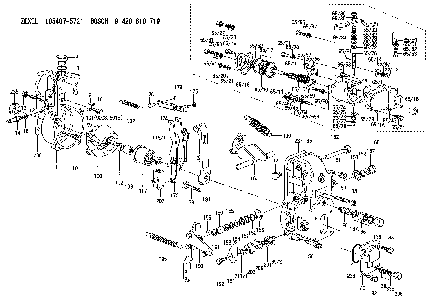
9 420 610 719
9420610719
ZEXEL
105407-5721
1054075721
Rating:
Scheme ###:
| 1. | [1] | 154000-5720 | GOVERNOR HOUSING |
| 3. | [1] | 029632-5070 | O-RING |
| 4. | [1] | 154007-2900 | CAPSULE |
| 9. | [1] | 154350-6000 | PLATE |
| 10. | [8] | 020106-2040 | BLEEDER SCREW M6P1L20 |
| 10. | [8] | 020106-2040 | BLEEDER SCREW M6P1L20 |
| 12. | [1] | 154010-0100 | FLAT-HEAD SCREW |
| 13. | [2] | 154011-0100 | HEXAGON NUT |
| 13. | [2] | 154011-0100 | HEXAGON NUT |
| 14. | [1] | 154012-1720 | BLEEDER SCREW |
| 15. | [1] | 014110-8440 | LOCKING WASHER |
| 35. | [1] | 154500-8120 | GOVERNOR COVER |
| 35/2. | [1] | 154321-0400 | BUSHING |
| 38. | [1] | 154031-4300 | FLAT-HEAD SCREW |
| 39. | [1] | 139208-0400 | UNION NUT |
| 47. | [1] | 154036-0300 | CAPSULE |
| 51. | [2] | 020106-5040 | BLEEDER SCREW |
| 53. | [1] | 154010-0100 | FLAT-HEAD SCREW |
| 56. | [4] | 020106-3840 | BLEEDER SCREW |
| 65. | [1] | 154421-0521 | MANIFOLD-PRESSURE COMP. |
| 65/1. | [1] | 154412-7820 | DIAPHRAGM HOUSING |
| 65/1A. | [1] | 154408-2901 | SPACER BUSHING |
| 65/1B. | [1] | 134009-0000 | SPACER BUSHING |
| 65/4. | [1] | 154413-0500 | BUSHING |
| 65/9. | [1] | 154412-4300 | COILED SPRING |
| 65/10. | [1] | 154400-8220 | DIAPHRAGM |
| 65/11. | [1] | 154400-6101 | STOP PIN |
| 65/14. | [1] | 154406-5500 | SLOTTED WASHER |
| 65/15. | [1] | 013020-6040 | UNION NUT M6P1H5 |
| 65/16. | [1] | 154411-5400 | COILED SPRING |
| 65/17. | [2] | 154413-2600 | GASKET |
| 65/18. | [1] | 154404-5000 | COVER |
| 65/19. | [1] | 020106-2040 | BLEEDER SCREW M6P1L20 |
| 65/20. | [2] | 029010-6310 | BLEEDER SCREW |
| 65/21. | [2] | 014110-6440 | LOCKING WASHER |
| 65/24. | [2] | 020106-2040 | BLEEDER SCREW M6P1L20 |
| 65/27. | [1] | 029731-0180 | EYE BOLT |
| 65/28. | [2] | 026510-1340 | GASKET D13.4&10.2T1 |
| 65/29. | [1] | 154390-1700 | GASKET |
| 65/43. | [1] | 154390-1800 | GASKET |
| 65/45. | [1] | 029331-8040 | GASKET |
| 65/46. | [1] | 154406-5800 | FLAT-HEAD SCREW |
| 65/47. | [1] | 014110-6440 | LOCKING WASHER |
| 65/50. | [1] | 154406-6800 | PLAIN WASHER |
| 65/51. | [1] | 154406-6901 | CONTROL LEVER |
| 65/52. | [1] | 014110-4440 | LOCKING WASHER |
| 65/53. | [1] | 010234-0820 | HEX-SOCKET-HEAD CAP SCREW |
| 65/54. | [1] | 013030-6040 | UNION NUT M6P1H3.6 |
| 65/55B. | [1] | 154404-1600 | FLAT-HEAD SCREW L26.00 |
| 65/56. | [1] | 029331-2130 | GASKET |
| 65/57. | [1] | 154406-6500 | FLAT-HEAD SCREW |
| 65/58. | [1] | 020106-2540 | BLEEDER SCREW M6P1L25 |
| 65/59. | [2] | 010006-7040 | BLEEDER SCREW M6P1L70 |
| 65/60. | [2] | 014110-6440 | LOCKING WASHER |
| 65/61. | [1] | 154035-1600 | CAP NUT |
| 65/62. | [1] | 154404-4400 | FLAT-HEAD SCREW |
| 65/63. | [1] | 013030-6040 | UNION NUT M6P1H3.6 |
| 65/64. | [2] | 026506-1040 | GASKET D9.9&6.2T1 |
| 65/66. | [1] | 139006-0900 | BLEEDER SCREW |
| 65/67. | [1] | 014110-6440 | LOCKING WASHER |
| 65/70. | [1] | 029240-6010 | UNION NUT M6P1.0H5* |
| 65/71. | [1] | 153141-1600 | BLEEDER SCREW |
| 65/72. | [1] | 139608-0000 | PACKING RING |
| 65/73. | [1] | 139605-0100 | PACKING RING |
| 65/74. | [1] | 154408-9000 | CONTROL LEVER |
| 65/75. | [1] | 154406-7500 | CONTROL LEVER |
| 65/76. | [1] | 154406-8000 | LEVER SHAFT |
| 65/77. | [1] | 029310-5200 | SHIM |
| 65/78. | [1] | 014020-8120 | PLAIN WASHER D16&8.5T1.2 |
| 65/79. | [1] | 154372-6500 | SAFETY PIN |
| 65/80. | [0] | 029310-8040 | SHIM D13.5&8T0.2 |
| 65/80B. | [0] | 029310-8050 | SHIM D13.5&8T0.5 |
| 65/81. | [1] | 025520-1210 | SPLIT PIN |
| 65/82. | [2] | 029300-8320 | SHIM |
| 65/83. | [1] | 154403-9900 | COILED SPRING |
| 65/84. | [1] | 154406-7700 | CONTROL LEVER |
| 65/85. | [1] | 014110-8440 | LOCKING WASHER |
| 65/86. | [1] | 013020-8140 | UNION NUT M8P1.25H6.5 |
| 80. | [1] | 154063-7300 | COVER |
| 82. | [2] | 029020-6210 | BLEEDER SCREW |
| 83. | [2] | 020006-1640 | BLEEDER SCREW M6P1L16 4T |
| 100. | [1] | 154101-0020 | FLYWEIGHT ASSEMBLY |
| 101. | [1] | 025803-1310 | WOODRUFF KEY |
| 102. | [1] | 029321-2020 | LOCKING WASHER |
| 103. | [1] | 029231-2030 | UNION NUT |
| 117. | [1] | 154123-2320 | SLIDING PIECE |
| 118/1. | [0] | 029311-0010 | SHIM D14&10.1T0.2 |
| 118/1. | [0] | 029311-0180 | SHIM D14&10.1T0.3 |
| 118/1. | [0] | 029311-0190 | SHIM D14&10.1T0.40 |
| 118/1. | [0] | 029311-0210 | SHIM D14&10.1T1 |
| 118/1. | [0] | 139410-0000 | SHIM D14.0&10.1T0.5 |
| 118/1. | [0] | 139410-0100 | SHIM D14.0&10.1T1.5 |
| 118/1. | [0] | 139410-3000 | SHIM D14&10.1T2.0 |
| 118/1. | [0] | 139410-3100 | SHIM D14&10.1T3.0 |
| 118/1. | [0] | 139410-3200 | SHIM D14&10.1T4.0 |
| 130. | [1] | 154150-2700 | GOVERNOR SPRING |
| 132. | [1] | 154154-0701 | COILED SPRING |
| 135. | [1] | 154158-1720 | HEADLESS SCREW |
| 136. | [1] | 154011-2700 | UNION NUT |
| 137. | [2] | 026512-1540 | GASKET D15.4&12.2T1.50 |
| 138. | [1] | 154159-1200 | CAP NUT |
| 150. | [1] | 154200-7120 | SWIVELLING LEVER |
| 151. | [1] | 154204-4300 | BUSHING |
| 152. | [2] | 029631-8020 | O-RING |
| 152. | [2] | 029631-8020 | O-RING |
| 153. | [2] | 016010-1640 | LOCKING WASHER |
| 153. | [2] | 016010-1640 | LOCKING WASHER |
| 154. | [1] | 139611-0000 | PACKING RING |
| 155. | [1] | 139411-0000 | SHIM |
| 156. | [0] | 029311-1070 | SHIM D16&11T0.5 |
| 157. | [1] | 154204-4400 | BUSHING |
| 159. | [1] | 025803-1310 | WOODRUFF KEY |
| 160. | [1] | 154206-2800 | BUSHING |
| 161. | [0] | 154206-0200 | PLAIN WASHER D19.5&11.2T1.0 |
| 170. | [1] | 154210-2720 | FORK LEVER |
| 174. | [1] | 154234-9620 | STRAP |
| 175. | [1] | 016010-0540 | LOCKING WASHER |
| 176. | [1] | 159231-4900 | BEARING PIN |
| 177. | [1] | 029310-5170 | SHIM D8&5.3T0.5 |
| 178. | [1] | 155402-3800 | SAFETY PIN |
| 181. | [1] | 154236-1500 | TENSIONING LEVER |
| 182. | [1] | 154237-1100 | BEARING PIN |
| 190. | [1] | 154345-5320 | CONTROL LEVER |
| 191. | [1] | 154367-6700 | CONTROL LEVER |
| 192. | [1] | 020006-1640 | BLEEDER SCREW M6P1L16 4T |
| 195. | [1] | 154314-2600 | COILED SPRING |
| 201. | [1] | 029631-0030 | O-RING &9.8W2.3 |
| 203. | [1] | 154322-0100 | CAP |
| 207. | [1] | 154326-5020 | CONTROL LEVER |
| 208. | [1] | 154327-7600 | COILED SPRING |
| 211/1. | [0] | 029311-0520 | SHIM D20.8&10.3T0.2 |
| 211/1. | [0] | 029311-0530 | SHIM D20.8&10.3T0.25 |
| 211/1. | [0] | 029311-0540 | SHIM D20.8&10.3T0.3 |
| 211/1. | [0] | 029311-0550 | SHIM D20.8&10.3T0.35 |
| 211/1. | [0] | 029311-0560 | SHIM D20.8&10.3T0.4 |
| 211/1. | [0] | 029311-0570 | SHIM D20.8&10.3T0.5 |
| 235. | [1] | 155412-5200 | IMPELLER WHEEL |
| 236. | [1] | 154371-5600 | GASKET |
| 237. | [1] | 154390-0300 | GASKET |
| 238. | [1] | 029635-2020 | O-RING |
| 335. | [2] | 026508-1140 | GASKET D11.4&8.2T1 |
| 336. | [1] | 154035-2000 | CAP NUT |
| 900S. | [1] | 025803-1310 | WOODRUFF KEY |
| 901S. | [1] | 025803-1610 | WOODRUFF KEY |
Include in #1:
106691-4091
as GOVERNOR
Cross reference number
Zexel num
Bosch num
Firm num
Name
Information:
Fig. 5-Output TerminalStart engine and run at approximately 1500 rpm. Connect voltmeter negative lead to alternator ground terminal and connect positive lead to alternator auxiliary terminal (Fig. 4). Voltmeter should read 15.4 volts. Now move voltmeter positive lead to alternator output terminal (Fig. 5). Voltage reading should be 14.4 volts.If voltage at auxiliary terminal is 15.4 volts, while at the output terminal it is 12 volts or battery voltage, the isolation diode is open. Replace it. Test No. 4 - Field Draw Test (Key Switch Off)Detach regulator and let hang by red and black wires. DO NOT allow regulator to touch the output terminal. If test ammeter is not equipped with a 1/4-ohm resistor, a 1/4-ohm resistor should be connected in series with the ammeter to protect the meter.
Fig. 6-Field Terminal - Test 4Disconnect green field wire from field terminal. Connect ammeter from output terminal (2, Fig. 6) to field terminal (1). Current reading should be 2 to 2.5 amps. If less than this, check brushes and slip rings. Test No. 5 - Checking Alternator and Regulator With Regulator Disconnected (Key Switch On - Engine Running)Disconnect the regulator from the connector. Disconnect the green wire from the field terminal. Connect a jumper wire from the output terminal (2, Fig. 6) to the field terminal (1). Connect voltmeter negative lead to ground terminal and connect voltmeter positive lead to regulator terminal (3).Start engine and run at slow idle. This test isolates the defect to either the alternator or regulator.If voltage at regulator terminal rises to 15-16 volts now, when it did not with regulator connected in Test No. 3, then the regulator is defective and should be replaced.If voltage does not rise at regulator terminal and the field circuit was okay in Test No. 4, then the stator or rectifier diodes are defective. See Section 16, Group 1672 for testing diodes and stator. Test No. 6 - Alternator OutputIf not using JDST-23 tong-type ammeter, disconnect wire from alternator output terminal and connect ammeter from alternator output terminal 2, Fig. 6 to starter solenoid "Bat" terminal. Connect voltmeter negative lead to ground and connect positive lead to output terminal (2, Fig. 6). Connect a carbon pile resistor (turned off) to the battery.Run engine at approximately 1400 rpm. Use a master tachometer to measure rpm. Adjust carbon pile to obtain maximum alternator output at 13 to 15 volts. Ammeter should read 25 amps or more for the 35 amp alternator and 43 amps for the 55 amp alternator. Test No. 7 - Testing RegulatorThe regulator must be checked with an alternator that is in good condition. If the alternator is questionable, check it as previously instructed.Connect voltmeter with 0.1 volt accuracy to the alternator output terminal and ground terminal (Fig. 5). With charged batteries and the regulator brought to operating temperature (fifteen minutes operation), the voltage should be as specified for the surrounding air temperature. See chart below. If battery is partially discharged, it may be necessary to connect a