Information governor
BOSCH
F 019 Z4E 359
f019z4e359
ZEXEL
105407-5690
1054075690
ISUZU
1157708820
1157708820

Rating:
Scheme ###:
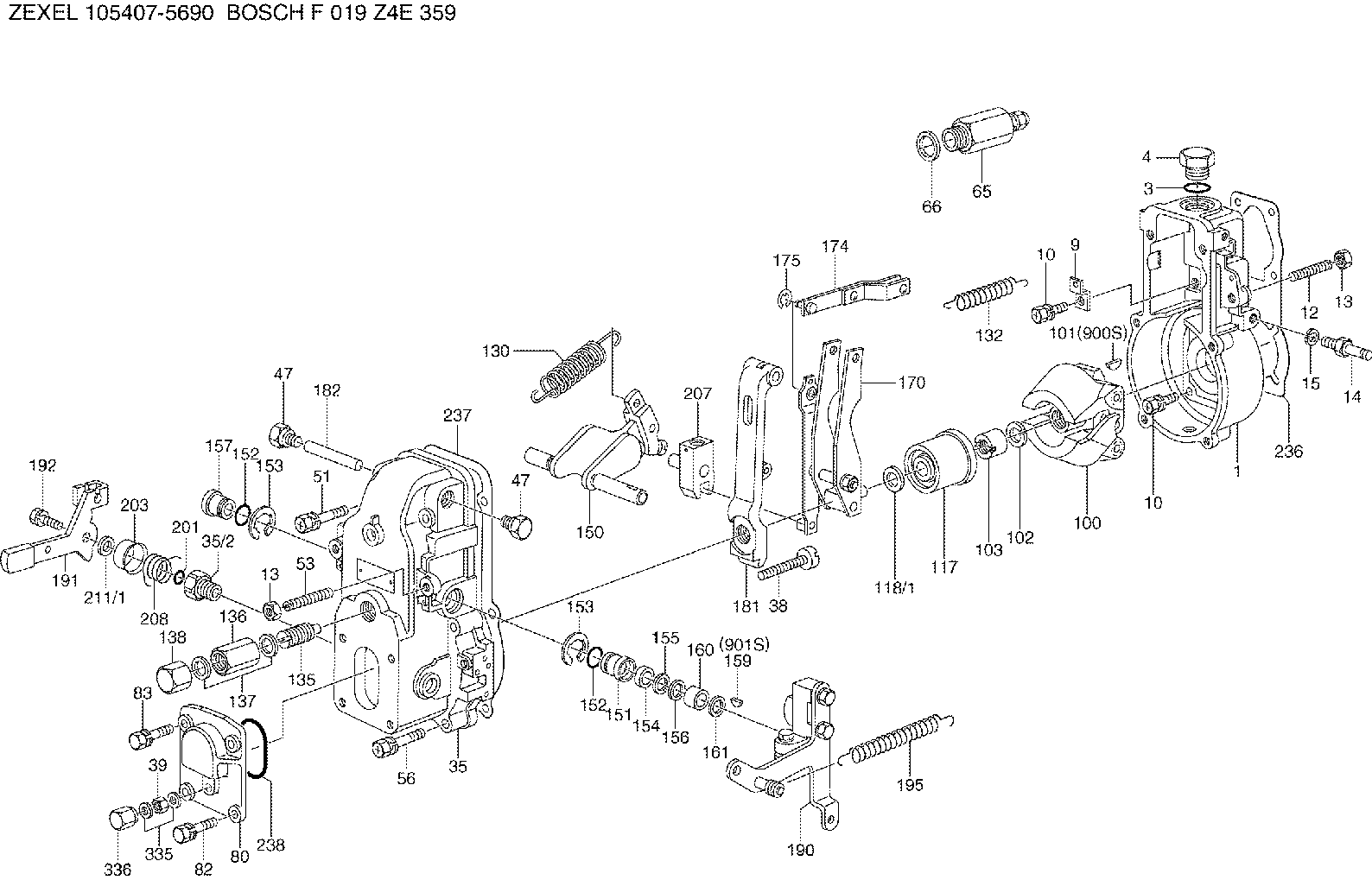
| 1. | [1] | 154000-4700 | GOVERNOR HOUSING |
| 3. | [1] | 029632-5070 | O-RING |
| 4. | [1] | 154007-2900 | CAPSULE |
| 9. | [1] | 154350-6000 | PLATE |
| 10. | [8] | 020106-2040 | BLEEDER SCREW |
| 10. | [8] | 020106-2040 | BLEEDER SCREW |
| 12. | [1] | 154010-1100 | FLAT-HEAD SCREW |
| 13. | [2] | 154011-0100 | HEXAGON NUT |
| 13. | [2] | 154011-0100 | HEXAGON NUT |
| 14. | [1] | 154012-1500 | BLEEDER SCREW |
| 15. | [1] | 014110-8440 | LOCKING WASHER D15.4&8.2T2 |
| 35. | [1] | 154500-1020 | GOVERNOR COVER |
| 35/2. | [1] | 154321-0400 | BUSHING |
| 38. | [1] | 154031-2400 | FLAT-HEAD SCREW |
| 39. | [1] | 139206-0600 | UNION NUT |
| 47. | [2] | 154036-0300 | CAPSULE |
| 47. | [2] | 154036-0300 | CAPSULE |
| 51. | [2] | 020106-5040 | BLEEDER SCREW |
| 53. | [1] | 154010-1100 | FLAT-HEAD SCREW |
| 56. | [4] | 020106-3840 | BLEEDER SCREW |
| 65. | [1] | 153021-3020 | STOPPING DEVICE |
| 66. | [1] | 026524-3040 | GASKET |
| 80. | [1] | 154063-1400 | COVER |
| 82. | [2] | 029020-6210 | BLEEDER SCREW |
| 83. | [2] | 020006-1640 | BLEEDER SCREW |
| 100. | [1] | 154101-0120 | FLYWEIGHT |
| 101. | [1] | 025803-1310 | WOODRUFF KEY 13 MM |
| 102. | [1] | 029321-2020 | LOCKING WASHER |
| 103. | [1] | 029231-2030 | UNION NUT |
| 117. | [1] | 154123-0120 | SLIDING PIECE |
| 118/1. | [0] | 029311-0010 | SHIM D14&10.1T0.2 |
| 118/1. | [0] | 029311-0180 | SHIM D14&10.1T0.3 |
| 118/1. | [0] | 029311-0190 | SHIM D14&10.1T0.40 |
| 118/1. | [0] | 029311-0210 | SHIM D14&10.1T1 |
| 118/1. | [0] | 139410-0000 | SHIM D14&10.1T0.5 |
| 118/1. | [0] | 139410-0100 | SHIM D14&10.1T1.5 |
| 118/1. | [0] | 139410-3000 | SHIM D14&10.1T2.0 |
| 118/1. | [0] | 139410-3100 | SHIM D14&10.1T3.0 |
| 118/1. | [0] | 139410-3200 | SHIM D14&10.1T4.0 |
| 130. | [1] | 154150-0400 | GOVERNOR SPRING |
| 132. | [1] | 154154-0500 | COILED SPRING |
| 135. | [1] | 154158-1320 | HEADLESS SCREW |
| 136. | [1] | 154011-1700 | UNION NUT |
| 137. | [2] | 026512-1540 | GASKET |
| 138. | [1] | 154159-1200 | CAP NUT |
| 150. | [1] | 154200-6920 | SWIVELLING LEVER |
| 151. | [1] | 154204-4300 | BUSHING |
| 152. | [2] | 029631-8020 | O-RING |
| 152. | [2] | 029631-8020 | O-RING |
| 153. | [2] | 016010-1640 | LOCKING WASHER |
| 153. | [2] | 016010-1640 | LOCKING WASHER |
| 154. | [1] | 139611-0000 | PACKING RING |
| 155. | [1] | 139411-0000 | SHIM |
| 156. | [0] | 029311-1070 | SHIM D16&11T0.5 |
| 157. | [1] | 154204-4400 | BUSHING |
| 159. | [1] | 025803-1310 | WOODRUFF KEY 13 MM |
| 160. | [1] | 154206-2800 | BUSHING |
| 161. | [0] | 154206-0200 | PLAIN WASHER D19.5&11.2T1.0 |
| 170. | [1] | 154210-9920 | FORK LEVER |
| 174. | [1] | 154230-2920 | STRAP |
| 175. | [1] | 016010-0540 | LOCKING WASHER |
| 181. | [1] | 154236-4100 | TENSIONING LEVER |
| 182. | [1] | 154237-0100 | BEARING PIN |
| 190. | [1] | 154303-5220 | CONTROL LEVER |
| 191. | [1] | 154304-6620 | CONTROL LEVER |
| 192. | [1] | 020006-1640 | BLEEDER SCREW |
| 195. | [1] | 154314-0200 | COILED SPRING |
| 201. | [1] | 029631-0030 | O-RING |
| 203. | [1] | 154322-0100 | CAP |
| 207. | [1] | 154326-5020 | CONTROL LEVER |
| 208. | [1] | 154327-7600 | COILED SPRING |
| 211/1. | [0] | 029311-0520 | SHIM D20.8&10.3T0.2 |
| 211/1. | [0] | 029311-0530 | SHIM D20.8&10.3T0.25 |
| 211/1. | [0] | 029311-0540 | SHIM D20.8&10.3T0.3 |
| 211/1. | [0] | 029311-0550 | SHIM D20.8&10.3T0.35 |
| 211/1. | [0] | 029311-0560 | SHIM D20.8&10.3T0.4 |
| 211/1. | [0] | 029311-0570 | SHIM D20.8&10.3T0.5 |
| 236. | [1] | 154371-5600 | GASKET |
| 237. | [1] | 154390-0300 | GASKET |
| 238. | [1] | 029635-2020 | O-RING |
| 335. | [2] | 026506-1040 | GASKET |
| 336. | [1] | 154035-1600 | CAP NUT |
| 900S. | [1] | 025803-1310 | WOODRUFF KEY 13 MM |
| 901S. | [1] | 025803-1610 | WOODRUFF KEY 16 MM |
Include in #1:
106671-1980
as GOVERNOR
Cross reference number
Zexel num
Bosch num
Firm num
Name
105407-5690
1157708820 ISUZU
GOVERNOR
K 14JB MECHANICAL GOVERNOR GOV RSV GOV
K 14JB MECHANICAL GOVERNOR GOV RSV GOV
Information:
Center Bushing Check new bushings using the table below. Commutator and Drive End Bushing Specifications*I.D. of bushing ... 0.6693 to 0.6704 in.(17.000 to 17.028 mm)Oil clearance** ... 0.0036 to 0.0070 in.(0.091 to 0.178 mm)Maximum clearance** ... 0.016 in.(0.41 mm)Bushing depth ... 0.008 to 0.022 in.(0.20 to 0.56 mm)*Reaming may be necessary after installation. Center Bushing SpecificationsI.D. of bushing ... 1.182 to 1.184 in.(30.02 to 30.07 mm)Maximum clearance** ... 0.0236 in.(0.599 mm)Bushing depth ... 0.017 to 0.032 in.(0.43 to 0.81 mm)**The clearance is the difference between the shaft and the I.D. of the bushing.Armature
Check armature for straightness. Runout should not exceed 0.006 inch (0.15 mm). Maximum commutator runout is 0.016 inch (0.41 mm). If necessary, turn commutator and undercut insulation to 1/32-inch (0.794 mm). Undercut should never be less than 0.008 inch (0.20 mm) Commutator O.D. must be 1.77 inches (45.0 mm) or more. Clean copper dust from between the segments.Check armature for opens, shorts and grounds. Burned edge of commutator indicates an open circuit. Short Circuit TestPlace the armature in a growler and hold a hacksaw blade above each slot while slowly rotating the armature. If a coil is shorted, the blade will be attracted to and repelled from the slot.A short circuit most often occurs because of copper dust or filings between two commutator segments. A short of this nature can be corrected by removal of such material.
Fig. 22-Armature Ground TestWith the ohmmeter set to read on its highest scale, place one test lead on the commutator and the other lead on the armature core or shaft (Fig. 22). If the test meter indicator swings towards zero, the armature is grounded. Replace armature.
Fig. 23-Open Circuit TestWith the ohmmeter set to read on its lowest scale, place one test lead on the commutator segment and the other test lead on an adjacent segment (Fig. 23). Repeat this operation for all segments by moving one lead at a time. If the test meter indicator does not swing to zero and remains stationary, the armature coil between these two segements is open. Replace armature.Burned commutator segments are usually an indication of an open circuited coil.Overrunning Clutch and Pinion
Do not immerse the overrunning clutch and pinion 4, Fig. 21 in a cleaning solvent. The unit has been prelubricated and solvent will wash lubricant away. It may be cleaned with a cloth moistened with a cleaning solvent and wiped dry.Rotate the pinion. Pinion gear should rotate smoothly (but not necessarily easily) in one direction, and should not rotate in the opposite direction.If the pinion gear does not rotate smoothly, or if it is worn, chipped, or burred, it should be replaced.Field Windings and Shunt Windings
Grounded Circuit Test (Fig. 24)
Fig. 24-Grounded Circuit TestRemove the screw and hang the eyelet terminal in the air. Using an ohmmeter set to read on its highest scale, place one test lead on the copper terminal bolt and the other lead on a clean spot of the field frame (Fig. 24). If the ohmmeter