Information governor
BOSCH
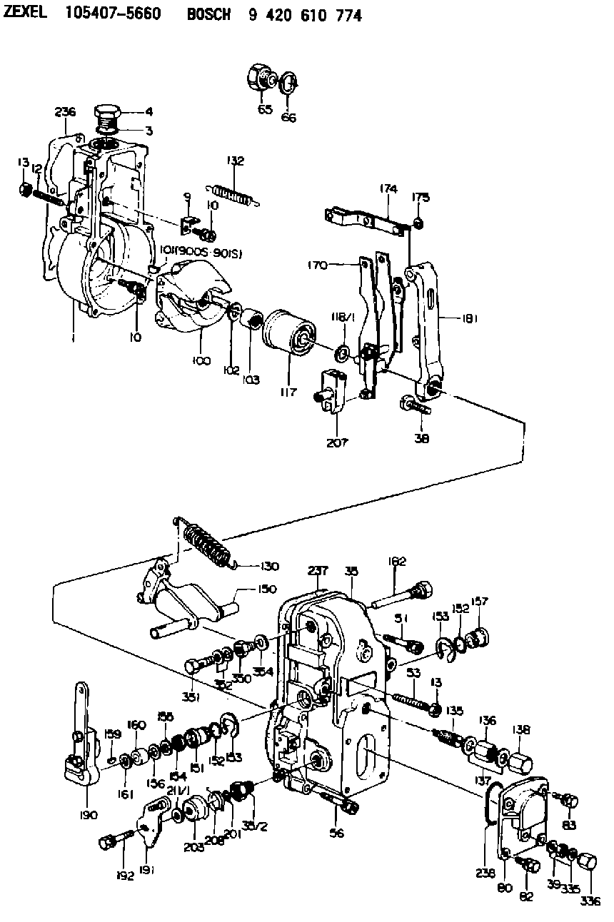
9 420 610 774
9420610774
ZEXEL
105407-5660
1054075660
Rating:
Scheme ###:
| 1. | [1] | 154000-4700 | GOVERNOR HOUSING |
| 3. | [1] | 029632-5070 | O-RING |
| 4. | [1] | 154007-2900 | CAPSULE |
| 9. | [1] | 154350-6000 | PLATE |
| 10. | [8] | 020106-2040 | BLEEDER SCREW M6P1L20 |
| 10. | [8] | 020106-2040 | BLEEDER SCREW M6P1L20 |
| 12. | [1] | 154010-0100 | FLAT-HEAD SCREW |
| 13. | [2] | 154011-0100 | HEXAGON NUT |
| 13. | [2] | 154011-0100 | HEXAGON NUT |
| 35. | [1] | 154500-8120 | GOVERNOR COVER |
| 35/2. | [1] | 154321-0400 | BUSHING |
| 38. | [1] | 154031-4300 | FLAT-HEAD SCREW |
| 39. | [1] | 139208-0400 | UNION NUT |
| 51. | [2] | 020106-5040 | BLEEDER SCREW |
| 53. | [1] | 154010-0200 | FLAT-HEAD SCREW |
| 56. | [4] | 020106-3840 | BLEEDER SCREW |
| 65. | [1] | 155404-1700 | CAP |
| 66. | [1] | 026524-3040 | GASKET |
| 80. | [1] | 154063-7300 | COVER |
| 82. | [2] | 029020-6210 | BLEEDER SCREW |
| 83. | [2] | 020006-1640 | BLEEDER SCREW M6P1L16 4T |
| 100. | [1] | 154101-0020 | FLYWEIGHT ASSEMBLY |
| 101. | [1] | 025803-1310 | WOODRUFF KEY |
| 102. | [1] | 029321-2020 | LOCKING WASHER |
| 103. | [1] | 029231-2030 | UNION NUT |
| 117. | [1] | 154123-2320 | SLIDING PIECE |
| 118/1. | [0] | 029311-0010 | SHIM D14&10.1T0.2 |
| 118/1. | [0] | 029311-0180 | SHIM D14&10.1T0.3 |
| 118/1. | [0] | 029311-0190 | SHIM D14&10.1T0.40 |
| 118/1. | [0] | 029311-0210 | SHIM D14&10.1T1 |
| 118/1. | [0] | 139410-0000 | SHIM D14.0&10.1T0.5 |
| 118/1. | [0] | 139410-0100 | SHIM D14.0&10.1T1.5 |
| 118/1. | [0] | 139410-3000 | SHIM D14&10.1T2.0 |
| 118/1. | [0] | 139410-3100 | SHIM D14&10.1T3.0 |
| 118/1. | [0] | 139410-3200 | SHIM D14&10.1T4.0 |
| 130. | [1] | 154150-0400 | GOVERNOR SPRING |
| 132. | [1] | 154154-0500 | COILED SPRING |
| 135. | [1] | 154158-1020 | HEADLESS SCREW |
| 136. | [1] | 154011-1700 | UNION NUT |
| 137. | [2] | 026512-1540 | GASKET D15.4&12.2T1.50 |
| 138. | [1] | 154159-1200 | CAP NUT |
| 150. | [1] | 154200-7020 | SWIVELLING LEVER |
| 151. | [1] | 154204-3000 | BUSHING |
| 152. | [2] | 139718-0200 | O-RING |
| 152. | [2] | 139718-0200 | O-RING |
| 153. | [2] | 016010-1640 | LOCKING WASHER |
| 153. | [2] | 016010-1640 | LOCKING WASHER |
| 154. | [1] | 139611-0300 | PACKING RING |
| 155. | [1] | 139411-0000 | SHIM |
| 156. | [0] | 029311-1070 | SHIM D16&11T0.5 |
| 157. | [1] | 154204-3100 | BUSHING |
| 159. | [1] | 025803-1310 | WOODRUFF KEY |
| 160. | [1] | 154206-2800 | BUSHING |
| 161. | [0] | 154206-0200 | PLAIN WASHER D19.5&11.2T1.0 |
| 170. | [1] | 154210-2720 | FORK LEVER |
| 174. | [1] | 154230-2920 | STRAP |
| 175. | [1] | 016010-0540 | LOCKING WASHER |
| 181. | [1] | 154236-4100 | TENSIONING LEVER |
| 182. | [1] | 154237-1700 | BEARING PIN |
| 190. | [1] | 154341-9720 | CONTROL LEVER |
| 191. | [1] | 154367-0920 | CONTROL LEVER |
| 192. | [1] | 020006-1640 | BLEEDER SCREW M6P1L16 4T |
| 201. | [1] | 139710-0500 | O-RING |
| 203. | [1] | 154322-0100 | CAP |
| 207. | [1] | 154326-5020 | CONTROL LEVER |
| 208. | [1] | 154327-7600 | COILED SPRING |
| 211/1. | [0] | 029311-0520 | SHIM D20.8&10.3T0.2 |
| 211/1. | [0] | 029311-0530 | SHIM D20.8&10.3T0.25 |
| 211/1. | [0] | 029311-0540 | SHIM D20.8&10.3T0.3 |
| 211/1. | [0] | 029311-0550 | SHIM D20.8&10.3T0.35 |
| 211/1. | [0] | 029311-0560 | SHIM D20.8&10.3T0.4 |
| 211/1. | [0] | 029311-0570 | SHIM D20.8&10.3T0.5 |
| 236. | [1] | 154371-5600 | GASKET |
| 237. | [1] | 154390-0300 | GASKET |
| 238. | [1] | 029635-2020 | O-RING |
| 335. | [2] | 026508-1140 | GASKET D11.4&8.2T1 |
| 336. | [1] | 154035-2000 | CAP NUT |
| 350. | [1] | 154036-1600 | ADAPTOR |
| 351. | [1] | 139806-0000 | EYE BOLT |
| 352. | [2] | 029340-6120 | GASKET |
| 354. | [1] | 029331-0090 | GASKET |
| 900S. | [1] | 025803-1310 | WOODRUFF KEY |
| 901S. | [1] | 025803-1610 | WOODRUFF KEY |
Cross reference number
Zexel num
Bosch num
Firm num
Name
Information:
Removal
Disconnect battery negative (-) cable at the battery terminal.Allow engine to cool.Drain cooling system.Remove alternator, fan belts, fan and sheet metal fan pulley.
Fig. 1-Bypass HoseDisconnect cooling system bypass hose (Fig. 1) at top of water pump.Disconnect lower radiator hose at water pump and engine oil cooler hose at lower rear of water pump (1, Fig. 2).
Fig. 2-Water Pump RemovalRemove water pump attaching hardware (2, Fig. 2) and remove water pump from engine.Disassembly
Fig. 3-Cover Plate RemovalRemove cover plate cap screws (1, Fig. 3). Lift cover plate (2) and gasket (3) off water pump.3-164D, 3-179D, 4-219D, 4-239D, 4-276D, or 6-329D Engine
Fig. 4-D01200AA PullerUsing D01200AA Puller (Fig. 4), remove pulley or pulley hub.
Fig. 5-JD262A Bearing DriverSupport housing from impeller end. Using JD262A Bearing Driver (Fig. 5), push bearing and impeller out of housing from pulley end.
Fig. 6-0.5 in. (13 mm) DriftSupport impeller from bearing side. Using a 0.5 in. (13 mm) drift (Fig. 6), push bearing shaft out of impeller.Lift seal off bearing shaft.4-239T, 4-276T, 6-359D, 6-359T, 6-414D, or 6-414T Engine
Fig. 7-D01200AA PullerUsing D01200AA Puller, remove pulley. IMPORTANT: Do not attempt to push shaft from pulley end. A flange in the bearing bore prevents bearing passage through housing.
Fig. 8-D01200AA PullerUsing D01200AA Puller, remove impeller.
Fig. 9-Bearing ShaftSupport pulley end of housing. Select a 0.5 in. (13 mm) diameter by 3.0 in. (76 mm) drift. Push against impeller end of bearing shaft (Fig. 9) to push bearing out of housing. IMPORTANT: Always replace a bearing that has been removed from pump.Repair
Fig. 10-Seal and InsertsInspect seal (2, Fig. 10) and ceramic insert (1) for damage. The lapped surfaces can not be grooved, chipped, cracked, or scratched.If there are traces of coolant on bearing or if there was leakage from drain hole in bottom of housing, the seal is leaking.To remove metal type seal, use a punch to drive it out of the housing from the bearing side.To remove rubber type seal, peel it out of the housing from the impeller side.If seal is replaced, also remove ceramic insert and cupped rubber insert from counterbore in impeller.Inspect housing for damage behind impeller. Replace housing and impeller if metal has been scrapped away. IMPORTANT: Always replace bearing that has been removed from pump.Assembly
IMPORTANT: Do not push against end of bearing shaft. Push against outer race only.
Fig. 11-JD262A or JDE74 Bearing DriverFor water pumps on engines 3-164D, 3-179D, 4-219D, 4-239D, 4-276D and 6-329D, use JD262A Bearing Driver (Fig. 11).For water pumps on engines 4-239T, 4-276T, 6-359D, 6-359T, 6-414D and 6-414T, use JDE74 Bearing Driver (Fig. 11).Push bearing into housing until outer end of bearing is flush with the housing. IMPORTANT: Do not touch lapped surface of seal.
Fig. 12-SealSparingly coat the flange portion of the seal with joint sealing compound. Press seal into housing by hand until flange bottoms on housing (Fig. 12). Wipe away any excess joint sealing compound.
Fig. 13-InsertsPlace ceramic insert in cupped rubber insert with "V" groove on ceramic insert toward cupped rubber insert. Be sure parts are dry and clean.Dip inserts in light oil