Information governor
BOSCH
9 420 610 826
9420610826
ZEXEL
105407-5650
1054075650
NISSAN-DIESEL
1910195315
1910195315
Rating:
Scheme ###:
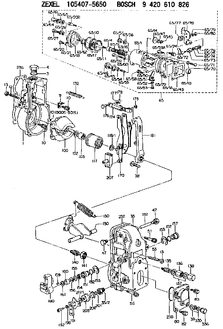
| 1. | [1] | 154000-4700 | GOVERNOR HOUSING |
| 3. | [1] | 029632-5070 | O-RING |
| 4. | [1] | 154007-2900 | CAPSULE |
| 9. | [1] | 154350-6000 | PLATE |
| 10. | [8] | 020106-2040 | BLEEDER SCREW M6P1L20 |
| 10. | [8] | 020106-2040 | BLEEDER SCREW M6P1L20 |
| 12. | [1] | 154010-0100 | FLAT-HEAD SCREW |
| 13. | [2] | 154011-0100 | HEXAGON NUT |
| 13. | [2] | 154011-0100 | HEXAGON NUT |
| 35. | [1] | 154500-1020 | GOVERNOR COVER |
| 35/2. | [1] | 154321-0400 | BUSHING |
| 38. | [1] | 154031-2400 | FLAT-HEAD SCREW |
| 39. | [1] | 139206-0600 | UNION NUT |
| 47. | [2] | 154036-0300 | CAPSULE |
| 47. | [2] | 154036-0300 | CAPSULE |
| 51. | [2] | 020106-5040 | BLEEDER SCREW |
| 53. | [1] | 154010-0100 | FLAT-HEAD SCREW |
| 56. | [4] | 020106-3840 | BLEEDER SCREW |
| 65. | [1] | 154421-0020 | MANIFOLD-PRESSURE COMP. |
| 65/1. | [1] | 154412-9520 | GOVERNOR HOUSING |
| 65/1A. | [1] | 154412-0201 | SPACER BUSHING |
| 65/1B. | [1] | 134009-0000 | SPACER BUSHING |
| 65/4. | [1] | 154413-0500 | BUSHING |
| 65/9. | [1] | 154414-8800 | COILED SPRING |
| 65/10. | [1] | 154400-8220 | DIAPHRAGM |
| 65/11. | [1] | 154412-4101 | STOP PIN |
| 65/14. | [1] | 154406-5500 | SLOTTED WASHER |
| 65/15. | [1] | 013020-6040 | UNION NUT M6P1H5 |
| 65/16. | [1] | 154411-8900 | COILED SPRING |
| 65/17. | [2] | 154413-2600 | GASKET |
| 65/18. | [1] | 154404-5000 | COVER |
| 65/20. | [2] | 029010-6310 | BLEEDER SCREW |
| 65/20B. | [1] | 020106-4540 | BLEEDER SCREW M6P1.0L45 |
| 65/21. | [2] | 014110-6440 | LOCKING WASHER |
| 65/24. | [2] | 020106-2040 | BLEEDER SCREW M6P1L20 |
| 65/27. | [1] | 029731-0180 | EYE BOLT |
| 65/28. | [2] | 026510-1340 | GASKET D13.4&10.2T1 |
| 65/29. | [1] | 154390-2200 | GASKET |
| 65/43. | [1] | 154390-2300 | GASKET |
| 65/45. | [1] | 029331-8040 | GASKET |
| 65/46. | [1] | 154406-5800 | FLAT-HEAD SCREW |
| 65/47. | [1] | 014110-6440 | LOCKING WASHER |
| 65/50. | [1] | 154406-6800 | PLAIN WASHER |
| 65/51. | [1] | 154412-9800 | CONTROL LEVER |
| 65/52. | [1] | 014110-4440 | LOCKING WASHER |
| 65/53. | [1] | 010234-0820 | HEX-SOCKET-HEAD CAP SCREW |
| 65/54. | [1] | 013030-6040 | UNION NUT M6P1H3.6 |
| 65/55. | [1] | 154404-1500 | FLAT-HEAD SCREW L22.00 |
| 65/55B. | [1] | 154404-1600 | FLAT-HEAD SCREW L26.00 |
| 65/56. | [1] | 029331-2130 | GASKET |
| 65/57. | [1] | 154406-6500 | FLAT-HEAD SCREW |
| 65/58. | [2] | 020106-2840 | BLEEDER SCREW |
| 65/58A. | [1] | 020106-1440 | BLEEDER SCREW M6P1.0L14 |
| 65/59. | [1] | 010006-7040 | BLEEDER SCREW M6P1L70 |
| 65/60. | [1] | 014110-6440 | LOCKING WASHER |
| 65/61. | [1] | 154035-1600 | CAP NUT |
| 65/62. | [1] | 154404-4400 | FLAT-HEAD SCREW |
| 65/63. | [1] | 013030-6040 | UNION NUT M6P1H3.6 |
| 65/64. | [2] | 026506-1040 | GASKET D9.9&6.2T1 |
| 65/70. | [1] | 029240-6010 | UNION NUT M6P1.0H5* |
| 65/71. | [1] | 029000-6290 | BLEEDER SCREW M6P1.0L19 |
| 65/72. | [1] | 154413-0021 | LEVER SHAFT |
| 65/73. | [1] | 154413-0100 | BUSHING |
| 65/74. | [1] | 139608-0000 | PACKING RING |
| 65/75. | [1] | 154413-0200 | PLAIN WASHER |
| 65/76. | [0] | 029310-8030 | SHIM D13.5&8T0.1 |
| 65/76B. | [0] | 029310-8040 | SHIM D13.5&8T0.2 |
| 65/77. | [1] | 154413-0301 | COILED SPRING |
| 65/78. | [1] | 154413-0400 | CONTROL LEVER |
| 65/79. | [1] | 014110-8440 | LOCKING WASHER |
| 65/80. | [1] | 013020-8140 | UNION NUT M8P1.25H6.5 |
| 80. | [1] | 154063-1400 | COVER |
| 82. | [2] | 029020-6210 | BLEEDER SCREW |
| 83. | [2] | 020006-1640 | BLEEDER SCREW M6P1L16 4T |
| 100. | [1] | 154101-0120 | FLYWEIGHT |
| 101. | [1] | 025803-1310 | WOODRUFF KEY |
| 102. | [1] | 029321-2020 | LOCKING WASHER |
| 103. | [1] | 029231-2030 | UNION NUT |
| 117. | [1] | 154123-0120 | SLIDING PIECE |
| 118/1. | [0] | 029311-0010 | SHIM D14&10.1T0.2 |
| 118/1. | [0] | 029311-0180 | SHIM D14&10.1T0.3 |
| 118/1. | [0] | 029311-0190 | SHIM D14&10.1T0.40 |
| 118/1. | [0] | 029311-0210 | SHIM D14&10.1T1 |
| 118/1. | [0] | 139410-0000 | SHIM D14.0&10.1T0.5 |
| 118/1. | [0] | 139410-0100 | SHIM D14.0&10.1T1.5 |
| 118/1. | [0] | 139410-3000 | SHIM D14&10.1T2.0 |
| 118/1. | [0] | 139410-3100 | SHIM D14&10.1T3.0 |
| 118/1. | [0] | 139410-3200 | SHIM D14&10.1T4.0 |
| 130. | [1] | 154150-2700 | GOVERNOR SPRING |
| 132. | [1] | 154154-0500 | COILED SPRING |
| 135. | [1] | 154158-1820 | HEADLESS SCREW |
| 136. | [1] | 154011-1700 | UNION NUT |
| 137. | [2] | 026512-1540 | GASKET D15.4&12.2T1.50 |
| 138. | [1] | 154159-1200 | CAP NUT |
| 140. | [1] | 154185-3620 | HEADLESS SCREW |
| 141. | [1] | 029201-6010 | UNION NUT |
| 150. | [1] | 154200-7120 | SWIVELLING LEVER |
| 151. | [1] | 154204-3000 | BUSHING |
| 152. | [2] | 029631-8020 | O-RING |
| 152. | [2] | 029631-8020 | O-RING |
| 153. | [2] | 016010-1640 | LOCKING WASHER |
| 153. | [2] | 016010-1640 | LOCKING WASHER |
| 154. | [1] | 139611-0000 | PACKING RING |
| 155. | [1] | 139411-0000 | SHIM |
| 156. | [0] | 029311-1070 | SHIM D16&11T0.5 |
| 157. | [1] | 154204-3100 | BUSHING |
| 159. | [1] | 025803-1310 | WOODRUFF KEY |
| 160. | [1] | 154206-2800 | BUSHING |
| 161. | [0] | 154206-0200 | PLAIN WASHER D19.5&11.2T1.0 |
| 170. | [1] | 154210-9920 | FORK LEVER |
| 174. | [1] | 154230-5120 | STRAP |
| 175. | [1] | 016010-0540 | LOCKING WASHER |
| 176. | [1] | 159231-4900 | BEARING PIN |
| 177. | [1] | 029310-5170 | SHIM D8&5.3T0.5 |
| 178. | [1] | 155402-3800 | SAFETY PIN |
| 181. | [1] | 154236-1500 | TENSIONING LEVER |
| 182. | [1] | 154237-0100 | BEARING PIN |
| 190. | [1] | 154340-0020 | CONTROL LEVER |
| 191. | [1] | 154364-7520 | CONTROL LEVER |
| 192. | [1] | 010206-1440 | HEX-SOCKET-HEAD CAP SCREW M6P1L14 |
| 198. | [1] | 029320-6010 | LOCKING WASHER |
| 201. | [1] | 029631-0030 | O-RING &9.8W2.3 |
| 203. | [1] | 154322-0100 | CAP |
| 207. | [1] | 154326-5020 | CONTROL LEVER |
| 208. | [1] | 154327-7600 | COILED SPRING |
| 211/1. | [0] | 029311-0520 | SHIM D20.8&10.3T0.2 |
| 211/1. | [0] | 029311-0530 | SHIM D20.8&10.3T0.25 |
| 211/1. | [0] | 029311-0540 | SHIM D20.8&10.3T0.3 |
| 211/1. | [0] | 029311-0550 | SHIM D20.8&10.3T0.35 |
| 211/1. | [0] | 029311-0560 | SHIM D20.8&10.3T0.4 |
| 211/1. | [0] | 029311-0570 | SHIM D20.8&10.3T0.5 |
| 236. | [1] | 154371-5600 | GASKET |
| 237. | [1] | 154390-0300 | GASKET |
| 238. | [1] | 029635-2020 | O-RING |
| 335. | [2] | 026506-1040 | GASKET D9.9&6.2T1 |
| 336. | [1] | 154035-1600 | CAP NUT |
| 900S. | [1] | 025803-1310 | WOODRUFF KEY |
| 901S. | [1] | 025803-1610 | WOODRUFF KEY |
Include in #1:
106671-5410
as GOVERNOR
Cross reference number
Zexel num
Bosch num
Firm num
Name
Information:
Fig. 4-Axial Bearing Movement CheckFasten dial indicator to turbine housing so that the indicator tip rests on the end of the shaft (Fig. 4).Move the shaft back and forth axially by hand. The total axial movement of the shaft should be 0.001 to 0.004 in. (0.03 to 0.10 mm). If not repair or replace unit.Repair
As each part is removed, place it in a clean protective container.Refer to Fig. 6 for part identification and relationship.
Fig. 5-Turbine Housing RemovalScribe a line on the mating surfaces of the turbine housing (1, Fig. 5) and center housing (2) to aid in alignment during reassembly.Remove the turbine housing-to-center housing cap screws (5, Fig. 5), lock plates (3), and clamps (4). Carefully remove turbine housing.
Fig. 6-Turbocharger Exploded View
Fig. 7-Removing Compressor (Impeller)Mount a suitable holding fixture (1, Fig. 7) (see Group 0499 Special Tools - Turbocharger) in a vise.Insert the turbine wheel into the fixture.Use a double universal socket to remove the compressor wheel retaining nut to avoid possible bending of the shaft.Remove the impeller (2, Fig. 7) from the shaft.
Fig. 8-Shaft and Wheel AssemblyRemove the turbine wheel and shaft assembly (3, Fig. 8) from the center housing keeping it centered until it is clear of the housing. Fig. 8 shows the turbine wheel assembly (1). The piston ring (2) can now be removed.Remove the back plate to center housing cap screw (16, Fig. 6) and lock plates (15).Carefully remove back plate by tapping with a soft mallet.
Fig. 9-Back Plate Assembly IMPORTANT: Back plate (2, Fig. 9) and the spring (1) are sold only as an assembly. The installed depth of the spring is a controlled dimension. Therefore, do not remove or replace the spring by itself. Cleaning can be done without removing the spring from the back plate.
Fig. 10-Removing Thrust Collar and Thrust WasherRemove the thrust collar (2, Fig. 10) and thrust washer (3) as shown in Fig. 10. Remove the O-ring (1) from housing and piston ring (4) from thrust collar.
Fig. 11-Retaining Ring and Bearing RemovalRemove retaining rings (2, Fig. 11) with a No. 501 Waldes Truarc Snap Ring Pliers, if snap rings are used, and bearings (1) from both sides of the center housing.Cleaning
Before cleaning, inspect parts for signs of burning, rubbing, or other damage which might not be evident after cleaning.Soak all parts in clean carbon solvent for approximately 25 minutes. After soaking use a stiff bristle brush to remove all dirt particles. Dry parts thoroughly. Normally, a light accumulation of carbon deposits will not affect turbine wheel operation.Inspection
Replace the following parts: O-ring (13, Fig. 6), lock plates (6, 15, and 21) piston rings (8 and 18), retaining rings (11), and all damaged nuts and bolts. If bearings and thrust washers show signs of nicks, scores, shellac deposits, or foreign material embedment, replace them.After cleaning, if any of the parts in the assembly show signs of rubbing, scoring, scratches, or seizure, replace them.Assembly
Be sure each part is clean before assembling. As parts are assembled, cover openings to prevent entry of dirt