Information governor
BOSCH
9 420 610 616
9420610616
ZEXEL
105407-5351
1054075351
HINO
223203330B
223203330b
Rating:
Scheme ###:
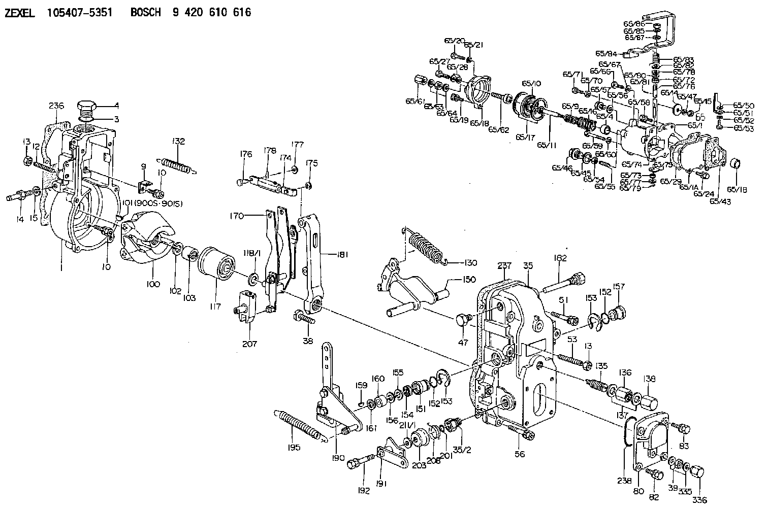
| 1. | [1] | 154000-4700 | GOVERNOR HOUSING |
| 3. | [1] | 029632-5070 | O-RING |
| 4. | [1] | 154007-2900 | CAPSULE |
| 9. | [1] | 154350-6000 | PLATE |
| 10. | [8] | 139006-4100 | BLEEDER SCREW |
| 10. | [8] | 139006-4100 | BLEEDER SCREW |
| 12. | [1] | 154010-0100 | FLAT-HEAD SCREW |
| 13. | [2] | 154011-0100 | HEXAGON NUT |
| 13. | [2] | 154011-0100 | HEXAGON NUT |
| 14. | [1] | 154013-1320 | BLEEDER SCREW |
| 15. | [1] | 014110-8440 | LOCKING WASHER |
| 35. | [1] | 154500-8120 | GOVERNOR COVER |
| 35/2. | [1] | 154321-0400 | BUSHING |
| 38. | [1] | 154031-4300 | FLAT-HEAD SCREW |
| 39. | [1] | 139208-0400 | UNION NUT |
| 47. | [1] | 154036-0300 | CAPSULE |
| 51. | [2] | 020106-5040 | BLEEDER SCREW |
| 53. | [1] | 154010-0100 | FLAT-HEAD SCREW |
| 56. | [4] | 020106-3840 | BLEEDER SCREW |
| 65. | [1] | 154420-5420 | MANIFOLD-PRESSURE COMP. |
| 65/1. | [1] | 154412-7820 | DIAPHRAGM HOUSING |
| 65/1A. | [1] | 154408-2901 | SPACER BUSHING |
| 65/1B. | [1] | 134009-0000 | SPACER BUSHING |
| 65/4. | [1] | 154413-0500 | BUSHING |
| 65/9. | [1] | 154412-4300 | COILED SPRING |
| 65/10. | [1] | 154400-8220 | DIAPHRAGM |
| 65/11. | [1] | 154400-6101 | STOP PIN |
| 65/14. | [1] | 154406-5500 | SLOTTED WASHER |
| 65/15. | [1] | 013020-6040 | UNION NUT M6P1H5 |
| 65/16. | [1] | 154402-6700 | COILED SPRING |
| 65/17. | [2] | 154413-2600 | GASKET |
| 65/18. | [1] | 154404-5000 | COVER |
| 65/19. | [1] | 020106-2040 | BLEEDER SCREW M6P1L20 |
| 65/20. | [2] | 029010-6310 | BLEEDER SCREW |
| 65/21. | [2] | 014110-6440 | LOCKING WASHER |
| 65/24. | [2] | 020106-2040 | BLEEDER SCREW M6P1L20 |
| 65/27. | [1] | 029731-0180 | EYE BOLT |
| 65/28. | [2] | 026510-1340 | GASKET D13.4&10.2T1 |
| 65/29. | [1] | 154390-1700 | GASKET |
| 65/43. | [1] | 154390-1800 | GASKET |
| 65/45. | [1] | 029331-8040 | GASKET |
| 65/46. | [1] | 154406-5800 | FLAT-HEAD SCREW |
| 65/47. | [1] | 014110-6440 | LOCKING WASHER |
| 65/50. | [1] | 154406-6800 | PLAIN WASHER |
| 65/51. | [1] | 154406-6901 | CONTROL LEVER |
| 65/52. | [1] | 014110-4440 | LOCKING WASHER |
| 65/53. | [1] | 010234-0820 | HEX-SOCKET-HEAD CAP SCREW |
| 65/54. | [1] | 013030-6040 | UNION NUT M6P1H3.6 |
| 65/55. | [1] | 154404-1500 | FLAT-HEAD SCREW L22.00 |
| 65/56. | [1] | 029331-2130 | GASKET |
| 65/57. | [1] | 154406-6500 | FLAT-HEAD SCREW |
| 65/58. | [1] | 020106-2540 | BLEEDER SCREW M6P1L25 |
| 65/59. | [2] | 010006-7040 | BLEEDER SCREW M6P1L70 |
| 65/60. | [2] | 014110-6440 | LOCKING WASHER |
| 65/61. | [1] | 154035-1600 | CAP NUT |
| 65/62. | [1] | 154404-4400 | FLAT-HEAD SCREW |
| 65/63. | [1] | 013030-6040 | UNION NUT M6P1H3.6 |
| 65/64. | [2] | 026506-1040 | GASKET D9.9&6.2T1 |
| 65/66. | [1] | 139006-0900 | BLEEDER SCREW |
| 65/67. | [1] | 014110-6440 | LOCKING WASHER |
| 65/70. | [1] | 029240-6010 | UNION NUT M6P1.0H5* |
| 65/71. | [1] | 153141-1600 | BLEEDER SCREW |
| 65/72. | [1] | 139608-0000 | PACKING RING |
| 65/73. | [1] | 139605-0100 | PACKING RING |
| 65/74. | [1] | 154408-9000 | CONTROL LEVER |
| 65/75. | [1] | 154406-7500 | CONTROL LEVER |
| 65/76. | [1] | 154406-8000 | LEVER SHAFT |
| 65/77. | [1] | 029310-5200 | SHIM |
| 65/78. | [1] | 014020-8120 | PLAIN WASHER D16&8.5T1.2 |
| 65/79. | [1] | 154372-6500 | SAFETY PIN |
| 65/80. | [0] | 029310-8040 | SHIM D13.5&8T0.2 |
| 65/80B. | [0] | 029310-8050 | SHIM D13.5&8T0.5 |
| 65/81. | [1] | 025520-1210 | SPLIT PIN |
| 65/82. | [2] | 029300-8320 | SHIM |
| 65/83. | [1] | 154403-9900 | COILED SPRING |
| 65/84. | [1] | 154413-6700 | CONTROL LEVER |
| 65/85. | [1] | 139308-1800 | PLAIN WASHER |
| 65/86. | [1] | 013020-8140 | UNION NUT M8P1.25H6.5 |
| 65/87. | [1] | 139308-1800 | PLAIN WASHER |
| 80. | [1] | 154063-7300 | COVER |
| 82. | [2] | 029020-6210 | BLEEDER SCREW |
| 83. | [2] | 020006-1640 | BLEEDER SCREW M6P1L16 4T |
| 100. | [1] | 154101-0120 | FLYWEIGHT |
| 101. | [1] | 025803-1310 | WOODRUFF KEY |
| 102. | [1] | 029321-2020 | LOCKING WASHER |
| 103. | [1] | 029231-2030 | UNION NUT |
| 117. | [1] | 154123-2320 | SLIDING PIECE |
| 118/1. | [0] | 029311-0010 | SHIM D14&10.1T0.2 |
| 118/1. | [0] | 029311-0180 | SHIM D14&10.1T0.3 |
| 118/1. | [0] | 029311-0190 | SHIM D14&10.1T0.40 |
| 118/1. | [0] | 029311-0210 | SHIM D14&10.1T1 |
| 118/1. | [0] | 139410-0000 | SHIM D14.0&10.1T0.5 |
| 118/1. | [0] | 139410-0100 | SHIM D14.0&10.1T1.5 |
| 118/1. | [0] | 139410-3000 | SHIM D14&10.1T2.0 |
| 118/1. | [0] | 139410-3100 | SHIM D14&10.1T3.0 |
| 118/1. | [0] | 139410-3200 | SHIM D14&10.1T4.0 |
| 130. | [1] | 154150-6400 | GOVERNOR SPRING |
| 132. | [1] | 154154-0800 | COILED SPRING |
| 135. | [1] | 154158-0820 | HEADLESS SCREW |
| 136. | [1] | 154011-2700 | UNION NUT |
| 137. | [2] | 026512-1540 | GASKET D15.4&12.2T1.50 |
| 138. | [1] | 154159-1200 | CAP NUT |
| 150. | [1] | 154200-7020 | SWIVELLING LEVER |
| 151. | [1] | 154204-4300 | BUSHING |
| 152. | [2] | 139718-0200 | O-RING |
| 152. | [2] | 139718-0200 | O-RING |
| 153. | [2] | 016010-1640 | LOCKING WASHER |
| 153. | [2] | 016010-1640 | LOCKING WASHER |
| 154. | [1] | 139611-0000 | PACKING RING |
| 155. | [1] | 139411-0000 | SHIM |
| 156. | [0] | 029311-1070 | SHIM D16&11T0.5 |
| 157. | [1] | 154204-4400 | BUSHING |
| 159. | [1] | 025803-1310 | WOODRUFF KEY |
| 160. | [1] | 154206-2800 | BUSHING |
| 161. | [0] | 154206-0200 | PLAIN WASHER D19.5&11.2T1.0 |
| 170. | [1] | 154210-9920 | FORK LEVER |
| 174. | [1] | 154234-9620 | STRAP |
| 175. | [1] | 016010-0540 | LOCKING WASHER |
| 176. | [1] | 159231-4900 | BEARING PIN |
| 177. | [1] | 029310-5170 | SHIM D8&5.3T0.5 |
| 178. | [1] | 155402-3800 | SAFETY PIN |
| 181. | [1] | 154236-4100 | TENSIONING LEVER |
| 182. | [1] | 154237-1100 | BEARING PIN |
| 190. | [1] | 154395-3120 | CONTROL LEVER |
| 191. | [1] | 154381-6220 | CONTROL LEVER |
| 192. | [1] | 020006-3540 | BLEEDER SCREW |
| 195. | [1] | 154314-2500 | COILED SPRING |
| 201. | [1] | 029631-0030 | O-RING &9.8W2.3 |
| 203. | [1] | 154322-0100 | CAP |
| 207. | [1] | 154326-5020 | CONTROL LEVER |
| 208. | [1] | 154327-7600 | COILED SPRING |
| 211/1. | [0] | 029311-0520 | SHIM D20.8&10.3T0.2 |
| 211/1. | [0] | 029311-0530 | SHIM D20.8&10.3T0.25 |
| 211/1. | [0] | 029311-0540 | SHIM D20.8&10.3T0.3 |
| 211/1. | [0] | 029311-0550 | SHIM D20.8&10.3T0.35 |
| 211/1. | [0] | 029311-0560 | SHIM D20.8&10.3T0.4 |
| 211/1. | [0] | 029311-0570 | SHIM D20.8&10.3T0.5 |
| 236. | [1] | 154371-5600 | GASKET |
| 237. | [1] | 154390-0300 | GASKET |
| 238. | [1] | 029635-2020 | O-RING |
| 335. | [2] | 026508-1140 | GASKET D11.4&8.2T1 |
| 336. | [1] | 154035-2000 | CAP NUT |
| 900S. | [1] | 025803-1310 | WOODRUFF KEY |
| 901S. | [1] | 025803-1610 | WOODRUFF KEY |
Include in #1:
106682-3002
as GOVERNOR
Cross reference number
Zexel num
Bosch num
Firm num
Name
105407-5351
223203330B HINO
GOVERNOR
K 14JB MECHANICAL GOVERNOR GOV RSV GOV
K 14JB MECHANICAL GOVERNOR GOV RSV GOV
Information:
PARTS NEEDED
Qty
Part Number Description
1 2744962 PUMP GP-F INJ -B
In order to allow equitable parts availability to all participating dealers, please limit your initial parts order to not exceed 2% of dealership population. This is an initial order recommendation only, and the ultimate responsibility for ordering the total number of parts needed to satisfy the program lies with the dealer.
ACTION REQUIRED
Replace the failed fuel injection pump. Refer to the engine's Disassembly and Assembly.
While carrying out "Fuel Injection Pump - Remove", please ensure that the fuel injection pump gear backlash is removed and the fuel injection pump locking bolt is tightened to a torque of 17 N.m (13 lb ft).
Fuel injection pumps that have not been locked correctly will have the claim rejected or debited.
After the new fuel injection pump has been installed, carry out checks for air in the fuel. Refer to the engine's Testing and Adjusting, "Air in Fuel - Test".
To ensure correct priming of the fuel system on first start-up, follow the procedure below.
1. Ensure that all low pressure fuel connections and high pressure fuel lines are installed correctly.
2. Set the throttle to the low idle position and ensure the parking brake is engaged
3. Crank the engine for 1 second to initiate the fuel priming sequence (do not start the engine)
4. Return ignition switch to the RUN position & listen for the fuel priming pump running
5. Leave the ignition key in the RUN position for three minutes.
6. Crank the engine with the throttle lever in the CLOSED position until the engine starts.
7. Run the engine at low idle for one minute.
8. Cycle the throttle lever from the low idle position to the high idle position three times. The cycle time for the throttle lever is one second to six seconds for one complete cycle.
9. Check for leaks in the fuel system.
Documentation Procedure
Please ensure that when submitting the claim the following documentation is provided.
1. Full details of the customer?s complaint and the symptoms witnessed.
2. Test work and diagnostic checks carried out to diagnose that the fuel injection pump is the part causing failure.
3. Results from the Testing and Adjusting, "Air in Fuel - Test". Please include photos of any air seen in the SIMS entry.
If the requested documentation is not provided, the claim may be rejected or debited.
SERVICE CLAIM ALLOWANCES
Product smu/age whichever comes first Caterpillar Dealer Suggested Customer Suggested
Parts % Labor Hrs% Parts % Labor Hrs% Parts % Labor Hrs%
0-3000 hrs,
0-36 mo 100.0% 100.0% 0.0% 0.0% 0.0% 0.0%
This is a 4.0-hour job
Refer to the Documentation Procedure in the Action Required for the Service Claim.
PARTS DISPOSITION
***** NACD *****
Hold all failed fuel injection pumps for a Parts Return Request (PRR). A PRR will be issued to you through the Send-It-Back process after the claim is submitted. Make