Information governor
BOSCH
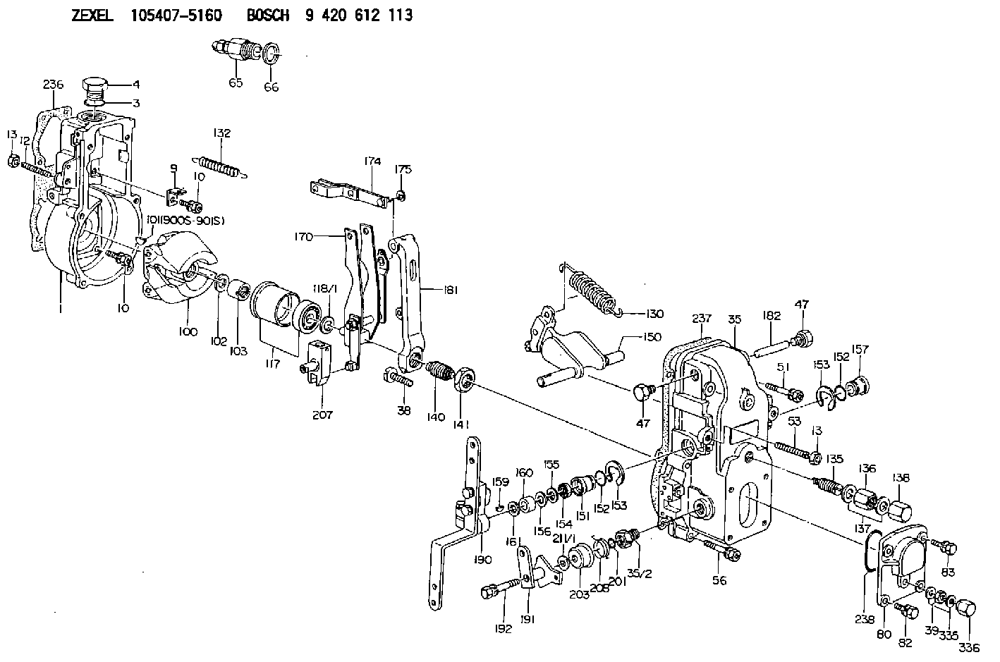
9 420 612 113
9420612113
ZEXEL
105407-5160
1054075160
HINO
223203340A
223203340a
Rating:
Scheme ###:
| 1. | [1] | 154000-4700 | GOVERNOR HOUSING |
| 3. | [1] | 029632-5070 | O-RING |
| 4. | [1] | 154007-2900 | CAPSULE |
| 9. | [1] | 154350-6000 | PLATE |
| 10. | [8] | 020106-2040 | BLEEDER SCREW M6P1L20 |
| 10. | [8] | 020106-2040 | BLEEDER SCREW M6P1L20 |
| 12. | [1] | 154010-1100 | FLAT-HEAD SCREW |
| 13. | [2] | 154011-0100 | HEXAGON NUT |
| 13. | [2] | 154011-0100 | HEXAGON NUT |
| 35. | [1] | 154500-1020 | GOVERNOR COVER |
| 35/2. | [1] | 154321-0400 | BUSHING |
| 38. | [1] | 154031-2400 | FLAT-HEAD SCREW |
| 39. | [1] | 139206-0600 | UNION NUT |
| 47. | [2] | 154036-0300 | CAPSULE |
| 47. | [2] | 154036-0300 | CAPSULE |
| 51. | [2] | 020106-5040 | BLEEDER SCREW |
| 53. | [1] | 154010-0500 | FLAT-HEAD SCREW |
| 56. | [4] | 020106-3840 | BLEEDER SCREW |
| 65. | [1] | 153021-5220 | STOPPING DEVICE |
| 66. | [1] | 026524-3040 | GASKET |
| 80. | [1] | 154063-1400 | COVER |
| 82. | [2] | 029020-6210 | BLEEDER SCREW |
| 83. | [2] | 020006-1640 | BLEEDER SCREW M6P1L16 4T |
| 100. | [1] | 154101-0020 | FLYWEIGHT ASSEMBLY |
| 101. | [1] | 025803-1310 | WOODRUFF KEY |
| 102. | [1] | 029321-2020 | LOCKING WASHER |
| 103. | [1] | 029231-2030 | UNION NUT |
| 117. | [1] | 154123-0120 | SLIDING PIECE |
| 118/1. | [0] | 029311-0010 | SHIM D14&10.1T0.2 |
| 118/1. | [0] | 029311-0180 | SHIM D14&10.1T0.3 |
| 118/1. | [0] | 029311-0190 | SHIM D14&10.1T0.40 |
| 118/1. | [0] | 029311-0210 | SHIM D14&10.1T1 |
| 118/1. | [0] | 139410-0000 | SHIM D14.0&10.1T0.5 |
| 118/1. | [0] | 139410-0100 | SHIM D14.0&10.1T1.5 |
| 118/1. | [0] | 139410-3000 | SHIM D14&10.1T2.0 |
| 118/1. | [0] | 139410-3100 | SHIM D14&10.1T3.0 |
| 118/1. | [0] | 139410-3200 | SHIM D14&10.1T4.0 |
| 130. | [1] | 154150-0400 | GOVERNOR SPRING |
| 132. | [1] | 154154-0701 | COILED SPRING |
| 135. | [1] | 154158-0820 | HEADLESS SCREW |
| 136. | [1] | 154011-2700 | UNION NUT |
| 137. | [2] | 026512-1540 | GASKET D15.4&12.2T1.50 |
| 138. | [1] | 154159-1200 | CAP NUT |
| 140. | [1] | 154177-3220 | HEADLESS SCREW |
| 141. | [1] | 029201-6010 | UNION NUT |
| 150. | [1] | 154200-7020 | SWIVELLING LEVER |
| 151. | [1] | 154204-3000 | BUSHING |
| 152. | [2] | 029631-8020 | O-RING |
| 152. | [2] | 029631-8020 | O-RING |
| 153. | [2] | 016010-1640 | LOCKING WASHER |
| 153. | [2] | 016010-1640 | LOCKING WASHER |
| 154. | [1] | 139611-0000 | PACKING RING |
| 155. | [1] | 139411-0000 | SHIM |
| 156. | [0] | 029311-1070 | SHIM D16&11T0.5 |
| 157. | [1] | 154204-3100 | BUSHING |
| 159. | [1] | 025803-1310 | WOODRUFF KEY |
| 160. | [1] | 154206-2800 | BUSHING |
| 161. | [0] | 154206-0200 | PLAIN WASHER D19.5&11.2T1.0 |
| 170. | [1] | 154210-2720 | FORK LEVER |
| 174. | [1] | 154230-2920 | STRAP |
| 175. | [1] | 016010-0540 | LOCKING WASHER |
| 181. | [1] | 154236-4100 | TENSIONING LEVER |
| 182. | [1] | 154237-0100 | BEARING PIN |
| 190. | [1] | 154341-8120 | CONTROL LEVER |
| 191. | [1] | 154380-6120 | CONTROL LEVER |
| 192. | [1] | 020006-3540 | BLEEDER SCREW |
| 201. | [1] | 029631-0030 | O-RING &9.8W2.3 |
| 203. | [1] | 154322-0100 | CAP |
| 207. | [1] | 154326-5020 | CONTROL LEVER |
| 208. | [1] | 154327-7600 | COILED SPRING |
| 211/1. | [0] | 029311-0520 | SHIM D20.8&10.3T0.2 |
| 211/1. | [0] | 029311-0530 | SHIM D20.8&10.3T0.25 |
| 211/1. | [0] | 029311-0540 | SHIM D20.8&10.3T0.3 |
| 211/1. | [0] | 029311-0550 | SHIM D20.8&10.3T0.35 |
| 211/1. | [0] | 029311-0560 | SHIM D20.8&10.3T0.4 |
| 211/1. | [0] | 029311-0570 | SHIM D20.8&10.3T0.5 |
| 236. | [1] | 154371-5600 | GASKET |
| 237. | [1] | 154390-0300 | GASKET |
| 238. | [1] | 029635-2020 | O-RING |
| 335. | [2] | 026506-1040 | GASKET D9.9&6.2T1 |
| 336. | [1] | 154035-1600 | CAP NUT |
| 900S. | [1] | 025803-1310 | WOODRUFF KEY |
| 901S. | [1] | 025803-1610 | WOODRUFF KEY |
Include in #1:
106672-3640
as GOVERNOR
Cross reference number
Zexel num
Bosch num
Firm num
Name
Information:
3406B and 3406C Non-Peec Engines
Steps 4 through 7 do not apply to PEEC engines.
Illustration 16. Install Lever Assembly
(1) 6N-3646 Lever. (2) 5P-0537 Washer. (3) 6V-8918 Bolt. (4) 9M-3858 Rack Preload Spring. (5) 1B-7182 Bolt.4. Install lever (1) with washer (2) and bolt (3).5. Install bolt (5) into hole as shown.6. Hook spring (4) between bolt (5) and lever (1).
Illustration 17. Install Rack Positioning Assembly
(1) 9U-5296 Rack Assembly. (2) Original cover mounting bolts or 4F-7957 Bolt.7. Install rack positioning assembly (1) with bolts (2). Use rack positioning assembly (1) as a "fuel ON" and "fuel OFF" control. Position the assembly to the full "fuel ON" position for all tests. Use the positioning assembly for rack adjustment.3406 Peec Engines
Steps 8 and 9 do not apply to Non-PEEC engines.
Illustration 18. Installing testing hardware for 3406 PEEC Engines
(1) 9U-5292 Rack Preload Assembly. (2) 9U-5120 Spanner Wrench. (3) 9U-5295 Positioning Assembly.8. Remove the BTM from the injection pump and install the 9U-5292 Rack Preload Assembly (1). Make sure the pin is properly located in the slot of the servo shaft. After installing the rack preload assembly, finger tighten the bolts.9. Remove the shut-off solenoid with a 9U-5120 Spanner Wrench (2) and install 9U-5295 Positioning Assembly (3). Use rack preload assembly (1) as a "fuel ON" and "fuel OFF" control. Position the assembly to the full "fuel ON" position for all tests. Use the positioning assembly for rack adjustment.Connect Hoses and Lines
Illustration 19. Connect Lube Oil Supply and Drain Hose
(1) 7G-7105 Hose. (2) 5P-6661 Fitting. (3) 9U-7709 Oil Drain Tube and two 5D-1026 Hose Clamps.
Illustration 20. Connect Fuel Supply and Return Lines
(4) 030-7947 Fitting, 3J-1907 O-ring Seal, and 7G-7105 Hose. (5) 8T-2160 Orifice Fitting, 3J-1907 O-ring Seal, and 7G-7105 Hose. (6) 9U-5298 Fuel Injection Line Tube Assembly (verify fuel line part number in TMI).1. Attach one end of hose (1) to the Lube Oil Supply fitting on the test stand. Attach the other end to the 5P-6661 Fitting on the rear support.2. Connect the oil drain tube (2) to the rear support and the test stand's stand-pipe with two hose clamps. On the AVM20-12C, the drain hose can be routed to the lube oil drain pan.3. Install fitting, O-ring, and hose (4) onto the fuel injection pump. Connect the other end of the hose to the "Test Oil Supply" connection on the test stand.4. Install fitting, O-ring, and hose (5) onto the fuel injection pump. Connect the other end of the hose to the "Test Oil Return" connection on the test stand.
Hold nut on 9U-6705 Master Nozzle when tightening fuel injection line tube assemblies (6). If the nut is not held in place during tightening, the master nozzle can be damaged.
5. Install six fuel injection line tube assemblies (6).Pre-Test Checks
1. Remove the lock-out on the electrical box, if installed.2. Release the Emergency Stop button.3. Start the bench and visually check for oil leaks from covers, hoses, etc.4. Check for oil flow through the drain tube. Also, check for oil flowing out of the oil