Information governor
BOSCH
9 420 611 671
9420611671
ZEXEL
105407-4874
1054074874
ISUZU
1157709860
1157709860

Rating:
Scheme ###:
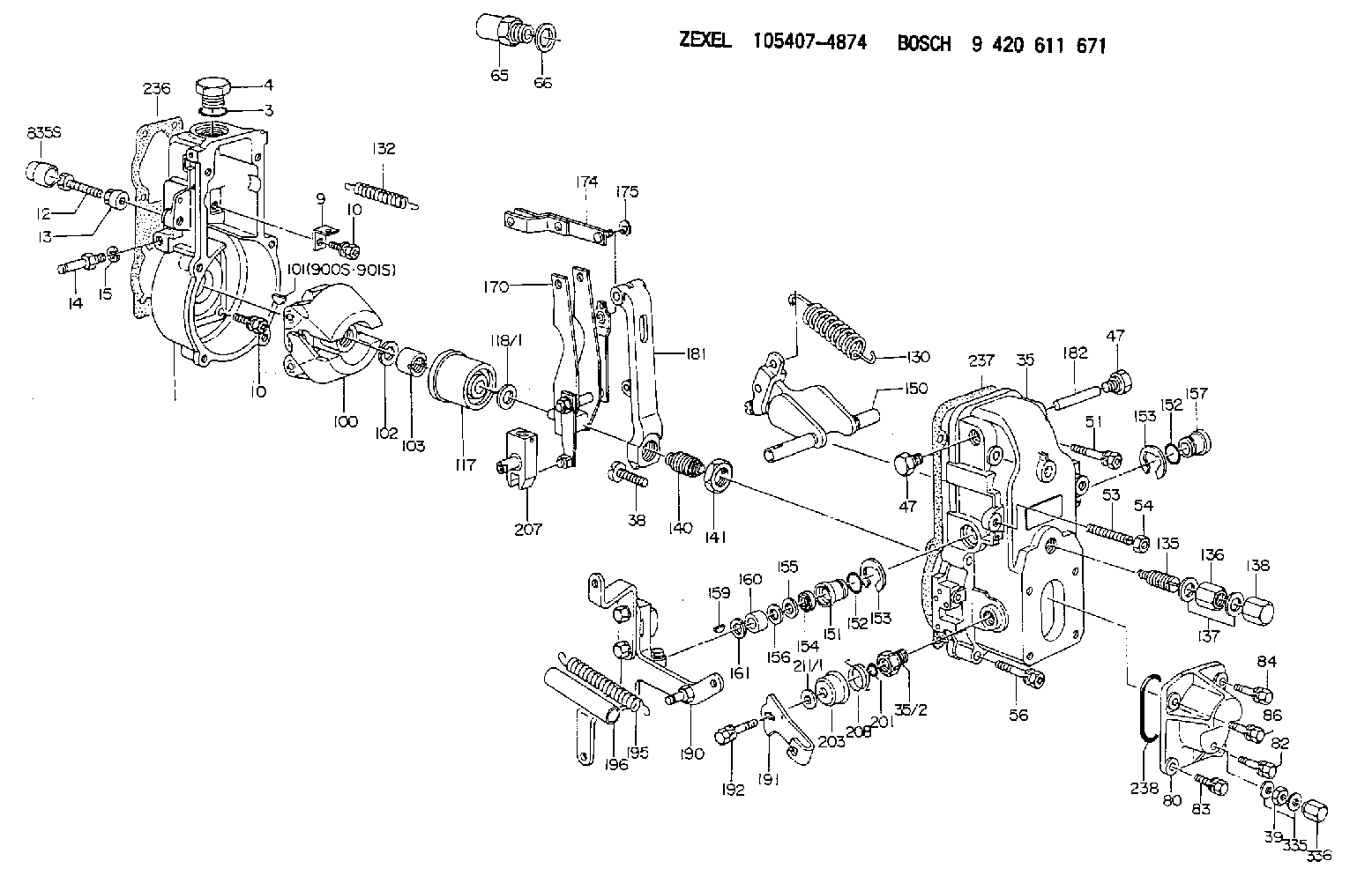
| 1. | [1] | 154000-4700 | GOVERNOR HOUSING |
| 3. | [1] | 029632-5070 | O-RING |
| 4. | [1] | 154007-2900 | CAPSULE |
| 9. | [1] | 154350-6000 | PLATE |
| 10. | [8] | 020106-2040 | BLEEDER SCREW M6P1L20 |
| 10. | [8] | 020106-2040 | BLEEDER SCREW M6P1L20 |
| 12. | [1] | 154010-8100 | BLEEDER SCREW M8P1.25L65 |
| 12B. | [1] | 154010-8900 | BLEEDER SCREW M8P1.25L67.5 |
| 13. | [1] | 154011-0100 | HEXAGON NUT |
| 14. | [1] | 154012-1500 | BLEEDER SCREW |
| 15. | [1] | 014110-8440 | LOCKING WASHER |
| 35. | [1] | 154500-1020 | GOVERNOR COVER |
| 35/2. | [1] | 154321-0400 | BUSHING |
| 38. | [1] | 154031-3000 | FLAT-HEAD SCREW |
| 39. | [1] | 139206-0600 | UNION NUT |
| 47. | [2] | 154036-0300 | CAPSULE |
| 47. | [2] | 154036-0300 | CAPSULE |
| 51. | [2] | 020106-5040 | BLEEDER SCREW |
| 53. | [1] | 154010-0200 | FLAT-HEAD SCREW |
| 54. | [1] | 154011-2300 | UNION NUT |
| 56. | [4] | 020106-3840 | BLEEDER SCREW |
| 65. | [1] | 155404-3400 | CAP |
| 66. | [1] | 026524-3040 | GASKET |
| 80. | [1] | 154063-5100 | COVER |
| 82. | [1] | 020006-1640 | BLEEDER SCREW M6P1L16 4T |
| 83. | [1] | 029020-6210 | BLEEDER SCREW |
| 84. | [1] | 020006-1640 | BLEEDER SCREW M6P1L16 4T |
| 86. | [1] | 020006-1640 | BLEEDER SCREW M6P1L16 4T |
| 100. | [1] | 154101-0020 | FLYWEIGHT ASSEMBLY |
| 101. | [1] | 025803-1310 | WOODRUFF KEY |
| 102. | [1] | 029321-2020 | LOCKING WASHER |
| 103. | [1] | 029231-2030 | UNION NUT |
| 117. | [1] | 154123-0120 | SLIDING PIECE |
| 118/1. | [0] | 029311-0010 | SHIM D14&10.1T0.2 |
| 118/1. | [0] | 029311-0180 | SHIM D14&10.1T0.3 |
| 118/1. | [0] | 029311-0190 | SHIM D14&10.1T0.40 |
| 118/1. | [0] | 029311-0210 | SHIM D14&10.1T1 |
| 118/1. | [0] | 139410-0000 | SHIM D14.0&10.1T0.5 |
| 118/1. | [0] | 139410-0100 | SHIM D14.0&10.1T1.5 |
| 118/1. | [0] | 139410-3000 | SHIM D14&10.1T2.0 |
| 118/1. | [0] | 139410-3100 | SHIM D14&10.1T3.0 |
| 118/1. | [0] | 139410-3200 | SHIM D14&10.1T4.0 |
| 130. | [1] | 154150-2900 | GOVERNOR SPRING |
| 132. | [1] | 154154-0701 | COILED SPRING |
| 135. | [1] | 154158-1720 | HEADLESS SCREW |
| 136. | [1] | 154011-1700 | UNION NUT |
| 137. | [2] | 026512-1540 | GASKET D15.4&12.2T1.50 |
| 138. | [1] | 154159-1200 | CAP NUT |
| 140. | [1] | 154178-9220 | HEADLESS SCREW |
| 141. | [1] | 029201-6010 | UNION NUT |
| 150. | [1] | 154200-7020 | SWIVELLING LEVER |
| 151. | [1] | 154204-3000 | BUSHING |
| 152. | [2] | 139718-0600 | O-RING |
| 152. | [2] | 139718-0600 | O-RING |
| 153. | [2] | 016010-1640 | LOCKING WASHER |
| 153. | [2] | 016010-1640 | LOCKING WASHER |
| 154. | [1] | 139611-0400 | PACKING RING |
| 155. | [1] | 139411-0000 | SHIM |
| 156. | [0] | 029311-1070 | SHIM D16&11T0.5 |
| 157. | [1] | 154204-3100 | BUSHING |
| 159. | [1] | 025803-1310 | WOODRUFF KEY |
| 160. | [1] | 154206-2800 | BUSHING |
| 161. | [0] | 154206-0200 | PLAIN WASHER D19.5&11.2T1.0 |
| 170. | [1] | 154218-2420 | FORK LEVER |
| 174. | [1] | 154230-2920 | STRAP |
| 175. | [1] | 016010-0540 | LOCKING WASHER |
| 181. | [1] | 154236-4100 | TENSIONING LEVER |
| 182. | [1] | 154237-0100 | BEARING PIN |
| 190. | [1] | 154395-1120 | CONTROL LEVER |
| 191. | [1] | 154381-0000 | CONTROL LEVER |
| 192. | [1] | 020006-1640 | BLEEDER SCREW M6P1L16 4T |
| 195. | [1] | 154314-0200 | COILED SPRING |
| 196. | [1] | 154156-1100 | TUBE |
| 201. | [1] | 139710-0300 | O-RING |
| 203. | [1] | 154322-0100 | CAP |
| 207. | [1] | 154326-5020 | CONTROL LEVER |
| 208. | [1] | 154327-7600 | COILED SPRING |
| 211/1. | [0] | 029311-0520 | SHIM D20.8&10.3T0.2 |
| 211/1. | [0] | 029311-0530 | SHIM D20.8&10.3T0.25 |
| 211/1. | [0] | 029311-0540 | SHIM D20.8&10.3T0.3 |
| 211/1. | [0] | 029311-0550 | SHIM D20.8&10.3T0.35 |
| 211/1. | [0] | 029311-0560 | SHIM D20.8&10.3T0.4 |
| 211/1. | [0] | 029311-0570 | SHIM D20.8&10.3T0.5 |
| 236. | [1] | 154371-5600 | GASKET |
| 237. | [1] | 154390-0300 | GASKET |
| 238. | [1] | 139752-0000 | O-RING |
| 335. | [2] | 026506-1040 | GASKET D9.9&6.2T1 |
| 336. | [1] | 154035-1600 | CAP NUT |
| 900S. | [1] | 025803-1310 | WOODRUFF KEY |
| 901S. | [1] | 025803-1610 | WOODRUFF KEY |
Include in #1:
106671-1766
as GOVERNOR
Cross reference number
Zexel num
Bosch num
Firm num
Name
105407-4874
1157709860 ISUZU
GOVERNOR
K 14JB MECHANICAL GOVERNOR GOV RSV GOV
K 14JB MECHANICAL GOVERNOR GOV RSV GOV
Information:
* For the frequency and timing of cleaning, refer to the relevant instruction manual. More frequent cleaning than necessary could damage the element or cause dust and foreign matter to be sucked into the engine.* Do not strike the element or hit it against another object to remove dust.* Do not blow compressed air against outside surfaces of the element.
Inspection Procedure Inspection: Outer Element* Shine some electric light inside the element.* Replace the element if thin spots or broken parts are evident in the filter paper, or if the packing at the top of the element is damaged. Also replace the element if the dust on the element is damp with oily smoke or soot, regardless of the replacement schedule. Inspection: Operation of dust indicator under specific negative pressure * Perform the following inspection and, if faulty, replace the dust indicator.* With no vacuum applied to the dust indicator, take measurement between the terminals 1 and 2. There should be no continuity.* Gradually apply vacuum to the dust indicator. Measure the vacuum when the continuity is made between the terminals 1 and 2.Turbocharger
Removal Sequence1 Turbocharger coupler2 Gasket3 Turbocharger insulator B4 Turbocharger insulator A5 Oil return pipe6 Gasket7 Eyebolt8 Oil pipe9 Turbocharger (See later sections.)10 Gasket*a: Exhaust manifoldX: Non-reusable parts Installation SequenceFollow the removal sequence in reverse.Tightening torque (Unit: N m {kgf m} Lubricant and/or sealant Installation Procedure Installation: Turbocharger* When installing the turbocharger, pour an appropriate amount of engine oil from the oil port so that each part operates smoothly.Turbocharger Disassembly Sequence1 Hose2 Actuator3 Coupling4 Turbine housing5 Snap ring6 Compressor cover7 O-ring8 Cartridge assemblyX: Non-resusable parts Assembly SequenceFollow the disassembly sequence in reverse.Service standards (Unit: mm) Tightening torque (Unit: N m {kgf m} Lubricant and/or sealant Work Before Removal Mating Marks* Draw a line across the coupling, turbine housing, compressor cover, and cartridge assembly. This line will serve as mating marks in the installation procedure. Removal Procedure Removal: Turbine housing
* Tap all around the end of the turbine housing with a rubber hammer or a similar tool, being careful not to damage the turbine housing.* Do not let the blades of the cartridge assembly hit the turbine housing, as they are easily bent.
Removal: Compressor Cover
* Tap all around the end of the turbine housing with a rubber hammer or a similar tool, being careful not damage the turbine housing.* Do not let the blades of the cartridge assembly hit the turbine housing, as they are easily bent.
Work after Disassembly Cleaning* Before cleaning the parts, carry out a visual inspection for any marks of burns or wear that may become difficult to find after the cleaning. If any defects are evident, replace the part(s).* Immerse the disassembled parts in an inflammable solvent (a 5 to 10 aqueous solution of Oil Clean from New Hope Co., Ltd.). Take out the parts from the solvent and dry them with compressed air. If there is any solid matter remaining on the parts, remove them with a plastic scraper or a bristle brush.
*