Information governor
BOSCH
F 019 Z1E 585
f019z1e585
ZEXEL
105407-4771
1054074771
NISSAN-DIESEL
1910196263
1910196263
Rating:
Scheme ###:
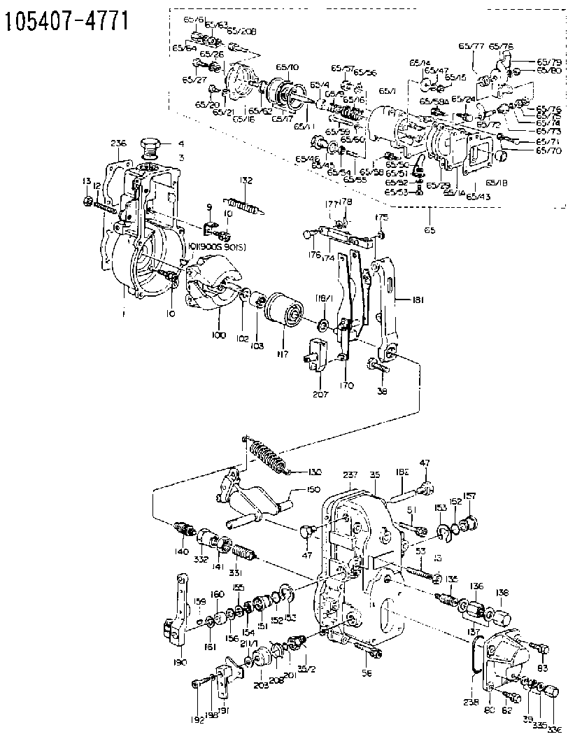
| 1. | [1] | 154000-4700 | GOVERNOR HOUSING |
| 3. | [1] | 029632-5070 | O-RING |
| 4. | [1] | 154007-2900 | CAPSULE |
| 9. | [1] | 154350-6000 | PLATE |
| 10. | [8] | 020106-2040 | BLEEDER SCREW M6P1L20 |
| 10. | [8] | 020106-2040 | BLEEDER SCREW M6P1L20 |
| 12. | [1] | 154010-0100 | FLAT-HEAD SCREW |
| 13. | [2] | 154011-0100 | HEXAGON NUT |
| 13. | [2] | 154011-0100 | HEXAGON NUT |
| 35. | [1] | 154500-1020 | GOVERNOR COVER |
| 35/2. | [1] | 154321-0400 | BUSHING |
| 38. | [1] | 154031-3000 | FLAT-HEAD SCREW |
| 39. | [1] | 139206-0600 | UNION NUT |
| 47. | [2] | 154036-0300 | CAPSULE |
| 47. | [2] | 154036-0300 | CAPSULE |
| 51. | [2] | 020106-5040 | BLEEDER SCREW |
| 53. | [1] | 154010-0200 | FLAT-HEAD SCREW |
| 56. | [4] | 020106-3840 | BLEEDER SCREW |
| 65. | [1] | 154420-0420 | MANIFOLD-PRESSURE COMP. |
| 65/1. | [1] | 154412-9520 | GOVERNOR HOUSING |
| 65/1A. | [1] | 154412-0201 | SPACER BUSHING |
| 65/1B. | [1] | 134009-0000 | SPACER BUSHING |
| 65/4. | [1] | 154413-0500 | BUSHING |
| 65/9. | [1] | 154402-3900 | COILED SPRING |
| 65/10. | [1] | 154400-8220 | DIAPHRAGM |
| 65/11. | [1] | 154412-4101 | STOP PIN |
| 65/14. | [1] | 154406-5500 | SLOTTED WASHER |
| 65/15. | [1] | 013020-6040 | UNION NUT M6P1H5 |
| 65/16. | [1] | 154411-6400 | COILED SPRING |
| 65/17. | [2] | 154413-2600 | GASKET |
| 65/18. | [1] | 154404-5000 | COVER |
| 65/20. | [2] | 029010-6310 | BLEEDER SCREW |
| 65/20B. | [1] | 020106-4540 | BLEEDER SCREW M6P1.0L45 |
| 65/21. | [2] | 014110-6440 | LOCKING WASHER |
| 65/24. | [2] | 020106-2040 | BLEEDER SCREW M6P1L20 |
| 65/27. | [1] | 029731-0180 | EYE BOLT |
| 65/28. | [2] | 026510-1340 | GASKET D13.4&10.2T1 |
| 65/29. | [1] | 154390-2200 | GASKET |
| 65/43. | [1] | 154390-2300 | GASKET |
| 65/45. | [1] | 029331-8040 | GASKET |
| 65/46. | [1] | 154406-5800 | FLAT-HEAD SCREW |
| 65/47. | [1] | 014110-6440 | LOCKING WASHER |
| 65/50. | [1] | 154406-6800 | PLAIN WASHER |
| 65/51. | [1] | 154412-9800 | CONTROL LEVER |
| 65/52. | [1] | 014110-4440 | LOCKING WASHER |
| 65/53. | [1] | 010234-0820 | HEX-SOCKET-HEAD CAP SCREW |
| 65/54. | [1] | 013030-6040 | UNION NUT M6P1H3.6 |
| 65/55. | [1] | 154404-1500 | FLAT-HEAD SCREW L22.00 |
| 65/55B. | [1] | 154404-1600 | FLAT-HEAD SCREW L26.00 |
| 65/56. | [1] | 029331-2130 | GASKET |
| 65/57. | [1] | 154406-6500 | FLAT-HEAD SCREW |
| 65/58. | [2] | 020106-2840 | BLEEDER SCREW |
| 65/58A. | [1] | 020106-1440 | BLEEDER SCREW M6P1.0L14 |
| 65/59. | [1] | 010006-7040 | BLEEDER SCREW M6P1L70 |
| 65/60. | [1] | 014110-6440 | LOCKING WASHER |
| 65/61. | [1] | 154035-1600 | CAP NUT |
| 65/62. | [1] | 154404-4400 | FLAT-HEAD SCREW |
| 65/63. | [1] | 013030-6040 | UNION NUT M6P1H3.6 |
| 65/64. | [2] | 026506-1040 | GASKET D9.9&6.2T1 |
| 65/70. | [1] | 029240-6010 | UNION NUT M6P1.0H5* |
| 65/71. | [1] | 029000-6290 | BLEEDER SCREW M6P1.0L19 |
| 65/72. | [1] | 154413-0021 | LEVER SHAFT |
| 65/73. | [1] | 154413-0100 | BUSHING |
| 65/74. | [1] | 139608-0000 | PACKING RING |
| 65/75. | [1] | 154413-0200 | PLAIN WASHER |
| 65/76. | [0] | 029310-8030 | SHIM D13.5&8T0.1 |
| 65/76B. | [0] | 029310-8040 | SHIM D13.5&8T0.2 |
| 65/77. | [1] | 154413-0301 | COILED SPRING |
| 65/78. | [1] | 154413-0400 | CONTROL LEVER |
| 65/79. | [1] | 014110-8440 | LOCKING WASHER |
| 65/80. | [1] | 013020-8140 | UNION NUT M8P1.25H6.5 |
| 80. | [1] | 154063-5100 | COVER |
| 82. | [2] | 029020-6210 | BLEEDER SCREW |
| 83. | [2] | 020006-1640 | BLEEDER SCREW M6P1L16 4T |
| 100. | [1] | 154100-9720 | FLYWEIGHT ASSEMBLY |
| 101. | [1] | 025803-1310 | WOODRUFF KEY |
| 102. | [1] | 029321-2020 | LOCKING WASHER |
| 103. | [1] | 029231-2030 | UNION NUT |
| 117. | [1] | 154123-0120 | SLIDING PIECE |
| 118/1. | [0] | 029311-0010 | SHIM D14&10.1T0.2 |
| 118/1. | [0] | 029311-0180 | SHIM D14&10.1T0.3 |
| 118/1. | [0] | 029311-0190 | SHIM D14&10.1T0.40 |
| 118/1. | [0] | 029311-0210 | SHIM D14&10.1T1 |
| 118/1. | [0] | 139410-0000 | SHIM D14.0&10.1T0.5 |
| 118/1. | [0] | 139410-0100 | SHIM D14.0&10.1T1.5 |
| 118/1. | [0] | 139410-3000 | SHIM D14&10.1T2.0 |
| 118/1. | [0] | 139410-3100 | SHIM D14&10.1T3.0 |
| 118/1. | [0] | 139410-3200 | SHIM D14&10.1T4.0 |
| 130. | [1] | 154150-0400 | GOVERNOR SPRING |
| 132. | [1] | 154154-0800 | COILED SPRING |
| 135. | [1] | 154158-0820 | HEADLESS SCREW |
| 136. | [1] | 154011-1700 | UNION NUT |
| 137. | [2] | 026512-1540 | GASKET D15.4&12.2T1.50 |
| 138. | [1] | 154159-1200 | CAP NUT |
| 140. | [1] | 154185-1320 | HEADLESS SCREW |
| 141. | [1] | 029201-6080 | UNION NUT |
| 150. | [1] | 154200-7020 | SWIVELLING LEVER |
| 151. | [1] | 154204-4300 | BUSHING |
| 152. | [2] | 029631-8020 | O-RING |
| 152. | [2] | 029631-8020 | O-RING |
| 153. | [2] | 016010-1640 | LOCKING WASHER |
| 153. | [2] | 016010-1640 | LOCKING WASHER |
| 154. | [1] | 139611-0000 | PACKING RING |
| 155. | [1] | 139411-0000 | SHIM |
| 156. | [0] | 029311-1070 | SHIM D16&11T0.5 |
| 157. | [1] | 154204-4400 | BUSHING |
| 159. | [1] | 025803-1310 | WOODRUFF KEY |
| 160. | [1] | 154206-2800 | BUSHING |
| 161. | [0] | 154206-0200 | PLAIN WASHER D19.5&11.2T1.0 |
| 170. | [1] | 154210-9920 | FORK LEVER |
| 174. | [1] | 154230-5120 | STRAP |
| 175. | [1] | 016010-0540 | LOCKING WASHER |
| 176. | [1] | 159231-4900 | BEARING PIN |
| 177. | [1] | 029310-5170 | SHIM D8&5.3T0.5 |
| 178. | [1] | 155402-3800 | SAFETY PIN |
| 181. | [1] | 154236-4100 | TENSIONING LEVER |
| 182. | [1] | 154237-0100 | BEARING PIN |
| 190. | [1] | 154309-6120 | CONTROL LEVER |
| 191. | [1] | 154364-7520 | CONTROL LEVER |
| 192. | [1] | 010206-1440 | HEX-SOCKET-HEAD CAP SCREW M6P1L14 |
| 198. | [1] | 029320-6010 | LOCKING WASHER |
| 201. | [1] | 029631-0030 | O-RING &9.8W2.3 |
| 203. | [1] | 154322-0100 | CAP |
| 207. | [1] | 154326-5020 | CONTROL LEVER |
| 208. | [1] | 154328-0700 | COILED SPRING |
| 211/1. | [0] | 029311-0520 | SHIM D20.8&10.3T0.2 |
| 211/1. | [0] | 029311-0530 | SHIM D20.8&10.3T0.25 |
| 211/1. | [0] | 029311-0540 | SHIM D20.8&10.3T0.3 |
| 211/1. | [0] | 029311-0550 | SHIM D20.8&10.3T0.35 |
| 211/1. | [0] | 029311-0560 | SHIM D20.8&10.3T0.4 |
| 211/1. | [0] | 029311-0570 | SHIM D20.8&10.3T0.5 |
| 236. | [1] | 154371-5600 | GASKET |
| 237. | [1] | 154390-0300 | GASKET |
| 238. | [1] | 029635-2020 | O-RING |
| 331. | [1] | 154179-1820 | HEADLESS SCREW |
| 332. | [1] | 029201-6010 | UNION NUT |
| 335. | [2] | 026506-1040 | GASKET D9.9&6.2T1 |
| 336. | [1] | 154035-1600 | CAP NUT |
| 900S. | [1] | 025803-1310 | WOODRUFF KEY |
| 901S. | [1] | 025803-1610 | WOODRUFF KEY |
Include in #1:
106651-5041
as GOVERNOR
Cross reference number
Zexel num
Bosch num
Firm num
Name
Information:
6. Full-load Quantity for Starting a warmed-up Engine
When the engine is warmed-up, it is not necessary to operate the lever (9) for additional fuel.7. Stopping the Engine
For stopping the engine, the starting and stopping lever (9) must be pulled beyond the starting position until it rests firmly against the stop. When pulling the lever slowly, the engine will speed up again before stopping.8. Operating the Tractor
The hydraulic governor of the distributor-type pump functions in the same manner as a mechanical governor (RSV governor) of an in-line pump. It is, however, more sensitive to response than the mechanical governor.Pump Illustrations
Fuel Circuit Of Distributor - Type Pump
Checking The Fuel-Injection Pump Drive And Replacing Components (as from 3 cylinder engine)
1. Check the gearwheel and hub or injection timer. If necessary, dismantle the gearwheel from the hub or from the injection timer.2. Renew the defective component.
7-492.1 Assemble the gearwheel and hub so that the punch mark registers with the groove in the hub.Fig. 7-49, right2.2 Assemble the gearwhell to the injection timer so that the recess in the former registers with the groove in the hub.Fig. 7-49, left Important:As from 1975, the hub was modified in the case of rigid drive.
7-502.3 In the case of in-line injection pump, mount gearwheel onto steel hub.Fig. 7-50, right2.4 In the case of distributor injection pump, mount gearwheel reversed onto the hub.Fig. 7-50 left Observe markings and angular degrees.Dismantling And Installing Injectors
Dismantling:
1. Dismantle leak-off line to injector. Disconnect injection delivery line on injection.2. Dismantle stirrup and remove thrust piece.
7-513. Remove injector using extracting device No. 150800.Fig. 7-51, Attention:In addition, use threaded piece No. 110050 in case of lateral connection of injection delivery line.Fig. 7-51, leftUse extractor No. 110030 in case of top connection of injection delivery line.Fig. 7-51, right
7-52On FL 912 W remove injector by special wrench No. 110010 plus insert No. 110020.Fig. 7-52
7-534. Remove joint washer from injector or from cylinder head, as the case may be. (Extractor No. 120630)Fig. 7-53, leftIn case of FL 912 W, remove heat insulating plate (using, for example, bent wire).Fig. 7-53, rightInstalling:
7-541. Stick new joint washer with grease (graphited side facing towards injector).Fig. 7-54 On FL 912 install heat guard as shown.Fig. 7-53, right2. Install injector.
7-553. Install thrust piece and place stirrup in position.Fig. 7-55, left4. Place washer with convex side facing stirrup and screw on nut.(See Specification Data)5. On FL 912 W align injector to injection pipe.Fig. 7-55, right
7-566. Tighten injector by special wrench No. 110010 plus insert No. 110020.Fig. 7-567. Tighten injector and fit leak-oil line with new sealing rings.Removing And Refitting Injector On Engine Provided With Exhaust Air Heating
Preliminary work:
Injector is removed.1. Stick by means of grease sealing ring to injector and insert the latter in the cylinder head.
7-572. Slip rubber seal on injector and the vertical pin (see arrow) for fixture.Fig. 7-57
7-583. Apply leak oil pan (arrow). Slip spring and spacer sleeve on pin for fixture.Fig. 7-584. Apply clamping piece and fixture.5. Apply washer the curved side of which must show towards fixture; screw on