Information governor
BOSCH
9 420 612 741
9420612741
ZEXEL
105407-2380
1054072380
YANMAR
12861961550
12861961550
Rating:
Scheme ###:
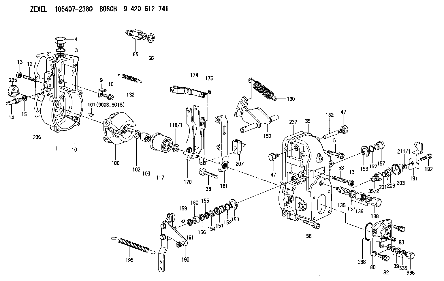
| 1. | [1] | 154000-5720 | GOVERNOR HOUSING |
| 3. | [1] | 029632-5070 | O-RING |
| 4. | [1] | 154007-2900 | CAPSULE |
| 9. | [1] | 154350-6000 | PLATE |
| 10. | [8] | 020106-2040 | BLEEDER SCREW M6P1L20 |
| 10. | [8] | 020106-2040 | BLEEDER SCREW M6P1L20 |
| 12. | [1] | 154010-0500 | FLAT-HEAD SCREW |
| 13. | [2] | 154011-0100 | HEXAGON NUT |
| 13. | [2] | 154011-0100 | HEXAGON NUT |
| 14. | [1] | 154012-1720 | BLEEDER SCREW |
| 15. | [1] | 014110-8440 | LOCKING WASHER |
| 35. | [1] | 154500-3020 | GOVERNOR COVER |
| 35/2. | [1] | 154321-0400 | BUSHING |
| 38. | [1] | 154031-2400 | FLAT-HEAD SCREW |
| 39. | [1] | 139206-0600 | UNION NUT |
| 47. | [2] | 154036-0300 | CAPSULE |
| 47. | [2] | 154036-0300 | CAPSULE |
| 51. | [2] | 020106-5040 | BLEEDER SCREW |
| 53. | [1] | 154010-0100 | FLAT-HEAD SCREW |
| 56. | [4] | 020106-3840 | BLEEDER SCREW |
| 65. | [1] | 153021-2220 | STOPPING DEVICE |
| 66. | [1] | 026524-3040 | GASKET |
| 80. | [1] | 154063-4520 | COVER |
| 82. | [2] | 029020-6210 | BLEEDER SCREW |
| 83. | [2] | 020006-1640 | BLEEDER SCREW M6P1L16 4T |
| 100. | [1] | 154101-0020 | FLYWEIGHT ASSEMBLY |
| 101. | [1] | 025803-1310 | WOODRUFF KEY |
| 102. | [1] | 029321-2020 | LOCKING WASHER |
| 103. | [1] | 029231-2030 | UNION NUT |
| 117. | [1] | 154123-0120 | SLIDING PIECE |
| 118/1. | [0] | 029311-0010 | SHIM D14&10.1T0.2 |
| 118/1. | [0] | 029311-0180 | SHIM D14&10.1T0.3 |
| 118/1. | [0] | 029311-0190 | SHIM D14&10.1T0.40 |
| 118/1. | [0] | 029311-0210 | SHIM D14&10.1T1 |
| 118/1. | [0] | 139410-0000 | SHIM D14.0&10.1T0.5 |
| 118/1. | [0] | 139410-0100 | SHIM D14.0&10.1T1.5 |
| 118/1. | [0] | 139410-3000 | SHIM D14&10.1T2.0 |
| 118/1. | [0] | 139410-3100 | SHIM D14&10.1T3.0 |
| 118/1. | [0] | 139410-3200 | SHIM D14&10.1T4.0 |
| 130. | [1] | 154150-0400 | GOVERNOR SPRING |
| 132. | [1] | 154154-0500 | COILED SPRING |
| 135. | [1] | 154158-1020 | HEADLESS SCREW |
| 136. | [1] | 154011-2700 | UNION NUT |
| 137. | [2] | 026512-1540 | GASKET D15.4&12.2T1.50 |
| 138. | [1] | 154159-1200 | CAP NUT |
| 150. | [1] | 154200-7020 | SWIVELLING LEVER |
| 151. | [1] | 154204-4300 | BUSHING |
| 152. | [2] | 029631-8020 | O-RING |
| 152. | [2] | 029631-8020 | O-RING |
| 153. | [2] | 016010-1640 | LOCKING WASHER |
| 153. | [2] | 016010-1640 | LOCKING WASHER |
| 154. | [1] | 139611-0000 | PACKING RING |
| 155. | [1] | 139411-0000 | SHIM |
| 156. | [0] | 029311-1070 | SHIM D16&11T0.5 |
| 157. | [1] | 154204-4400 | BUSHING |
| 159. | [1] | 025803-1310 | WOODRUFF KEY |
| 160. | [1] | 154206-2800 | BUSHING |
| 161. | [0] | 154206-0200 | PLAIN WASHER D19.5&11.2T1.0 |
| 170. | [1] | 154211-4320 | FORK LEVER |
| 174. | [1] | 154230-2920 | STRAP |
| 175. | [1] | 016010-0540 | LOCKING WASHER |
| 181. | [1] | 154236-4100 | TENSIONING LEVER |
| 182. | [1] | 154237-0100 | BEARING PIN |
| 190. | [1] | 154345-5320 | CONTROL LEVER |
| 191. | [1] | 154304-2800 | CONTROL LEVER |
| 192. | [1] | 020006-1640 | BLEEDER SCREW M6P1L16 4T |
| 195. | [1] | 154314-2600 | COILED SPRING |
| 201. | [1] | 029631-0030 | O-RING &9.8W2.3 |
| 203. | [1] | 154322-0100 | CAP |
| 207. | [1] | 154326-5120 | CONTROL LEVER |
| 208. | [1] | 154327-7300 | COILED SPRING |
| 211/1. | [0] | 029311-0520 | SHIM D20.8&10.3T0.2 |
| 211/1. | [0] | 029311-0530 | SHIM D20.8&10.3T0.25 |
| 211/1. | [0] | 029311-0540 | SHIM D20.8&10.3T0.3 |
| 211/1. | [0] | 029311-0550 | SHIM D20.8&10.3T0.35 |
| 211/1. | [0] | 029311-0560 | SHIM D20.8&10.3T0.4 |
| 211/1. | [0] | 029311-0570 | SHIM D20.8&10.3T0.5 |
| 235. | [1] | 155412-5200 | IMPELLER WHEEL |
| 236. | [1] | 154371-5600 | GASKET |
| 237. | [1] | 154390-0300 | GASKET |
| 238. | [1] | 029635-2020 | O-RING |
| 335. | [2] | 026506-1040 | GASKET D9.9&6.2T1 |
| 336. | [1] | 154035-1600 | CAP NUT |
| 900S. | [1] | 025803-1310 | WOODRUFF KEY |
| 901S. | [1] | 025803-1610 | WOODRUFF KEY |
Cross reference number
Zexel num
Bosch num
Firm num
Name
105407-2380
12861961550 YANMAR
GOVERNOR
K 14JB MECHANICAL GOVERNOR GOV RSV GOV
K 14JB MECHANICAL GOVERNOR GOV RSV GOV
Information:
Illustration 5 g06198951
70-Pin connector
(5) Pin 4
(6) Pin 24
Illustration 6 g06198953
40-Pin connector
(7) Pin 4
(8) Pin 24
Using the appropriate terminal extraction tool, remove the red and black wires from positions 4 and 24 of the connector. Refer to Illustration 5 and 6.
Route the extracted wires out of the engine harness and insert the wires into 3E-3370 Connector Receptacle As supplied with 517-0586 Engine Harness As. Red wire in position 1 and Black wire in position 2.Note: Minor cutting of the boot may be required.
Install the Red wire from 517-0586 Engine Harness As into position 4 of the Machine Interface Connector and install the Black wire into position 24 of the connector.
Illustration 7 g06237613
70 Pin Harness
(A) Pin 4 From Machine Interface Harness Connector
(B) Pin 24 From Machine Interface Harness Connector
(C) Pyrometer Harness Interface Connector
(D) Machine Interface Connector
Illustration 8 g06237606
40 Pin Harness
(A) Pin 4 From Machine Interface Harness Connector
(B) Pin 24 From Machine Interface Harness Connector
(E) Flying Power Leads from 514-3813 Harness As to 2 Pin Connector
(F) Machine Interface Connector
If the Pyrometer Interface Harness connector is a 70 pin, Route 517-0586 Engine Harness As to the Pyrometer Harness Interface connector and install Red wire into position 70 and the Black wire into position 69. If the Pyrometer Interface Harness connector is a 40 pin, install the Red wire into pin 1 of a 2-pin receptacle and the Black wire into pin 2. This connector will then connect to G-C3 of 514-3813 Engine Harness As.
With the engine powered, use a digital multimeter to verify that 24V power is present at the Pyrometer Harness Interface connector.Installation of 510-4068 Electronic Control Gp (Pyrometer)
Attach 489-3081 Harness As to 510-4068 Electronic Control Gp (Pyrometer) and the Pyrometer Interface Connector. Using 489-3081 Engine Harness As as a gauge, temporarily install the module on an appropriate place as per the choice of installer.Installation of 505-1731 Engine Harness As
If the engine under test is a 16 cylinder instead of a 20 cylinder, 505-1731 Engine Harness As can be installed between 489-3081 Engine Harness As and 510-4068 Electronic Control Gp.Installation of 489-3081 Engine Harness As
Perform the following procedure to install 489-3081 Engine Harness As:
Install 504-3341 Engine Harness As on the service port connector of 489-3081 Engine Harness As.
Route 504-3341 Engine Harness As to a safe location before performing tests.Note: Attach 140-9442 "Y" Adapter Cable As in order to see all the machine ECMs. Connect 504-3341 Monitor Harness As to "Y", connect other leg to Machine Service port and the third leg to Communication Adapter.Overview and Configuration On Caterpillar Electronic Technician (Cat ET)
This section will describe the overview and configuration setting on Cat ET.Cat ET Screen - Standard View
Perform the following instructions once the system is installed:
Connect to communications adapter and launch Cat ET.
Illustration 9 g06198935
After connecting, under "Available ECM(s)" select "Digital Pyrometer #1".
Illustration 10 g06199349
(9) Status button
Select the "Status" (9) button in the toolbar and then the parameters of "Digital Pyrometer #1" will appear.
Selecting "Engine Cylinder Temperature - 1"