Information governor
BOSCH
9 420 610 902
9420610902
ZEXEL
105407-2310
1054072310
HINO
223202130A
223202130a
Rating:
Scheme ###:
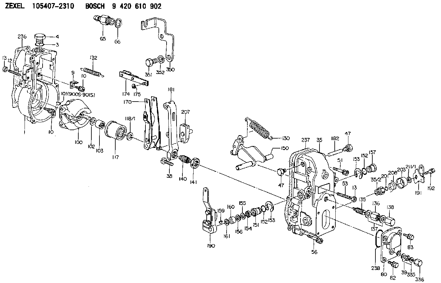
| 1. | [1] | 154000-4700 | GOVERNOR HOUSING |
| 3. | [1] | 029632-5070 | O-RING |
| 4. | [1] | 154007-2900 | CAPSULE |
| 9. | [1] | 154350-6000 | PLATE |
| 10. | [8] | 020106-2040 | BLEEDER SCREW M6P1L20 |
| 10. | [8] | 020106-2040 | BLEEDER SCREW M6P1L20 |
| 12. | [1] | 154010-1100 | FLAT-HEAD SCREW |
| 13. | [2] | 154011-0100 | HEXAGON NUT |
| 13. | [2] | 154011-0100 | HEXAGON NUT |
| 35. | [1] | 154500-3020 | GOVERNOR COVER |
| 35/2. | [1] | 154321-0400 | BUSHING |
| 38. | [1] | 154031-2400 | FLAT-HEAD SCREW |
| 39. | [1] | 139206-0600 | UNION NUT |
| 47. | [2] | 154036-0300 | CAPSULE |
| 47. | [2] | 154036-0300 | CAPSULE |
| 51. | [2] | 020106-5040 | BLEEDER SCREW |
| 53. | [1] | 154010-0100 | FLAT-HEAD SCREW |
| 56. | [4] | 020106-3840 | BLEEDER SCREW |
| 65. | [1] | 153021-3020 | STOPPING DEVICE |
| 66. | [1] | 026524-3040 | GASKET |
| 80. | [1] | 154063-1400 | COVER |
| 82. | [2] | 029020-6210 | BLEEDER SCREW |
| 83. | [2] | 020006-1640 | BLEEDER SCREW M6P1L16 4T |
| 100. | [1] | 154101-0020 | FLYWEIGHT ASSEMBLY |
| 101. | [1] | 025803-1310 | WOODRUFF KEY |
| 102. | [1] | 029321-2020 | LOCKING WASHER |
| 103. | [1] | 029231-2030 | UNION NUT |
| 117. | [1] | 154123-0120 | SLIDING PIECE |
| 118/1. | [0] | 029311-0010 | SHIM D14&10.1T0.2 |
| 118/1. | [0] | 029311-0180 | SHIM D14&10.1T0.3 |
| 118/1. | [0] | 029311-0190 | SHIM D14&10.1T0.40 |
| 118/1. | [0] | 029311-0210 | SHIM D14&10.1T1 |
| 118/1. | [0] | 139410-0000 | SHIM D14.0&10.1T0.5 |
| 118/1. | [0] | 139410-0100 | SHIM D14.0&10.1T1.5 |
| 118/1. | [0] | 139410-3000 | SHIM D14&10.1T2.0 |
| 118/1. | [0] | 139410-3100 | SHIM D14&10.1T3.0 |
| 118/1. | [0] | 139410-3200 | SHIM D14&10.1T4.0 |
| 130. | [1] | 154150-0400 | GOVERNOR SPRING |
| 132. | [1] | 154154-0500 | COILED SPRING |
| 135. | [1] | 154158-1720 | HEADLESS SCREW |
| 136. | [1] | 154011-1700 | UNION NUT |
| 137. | [2] | 026512-1540 | GASKET D15.4&12.2T1.50 |
| 138. | [1] | 154159-1200 | CAP NUT |
| 140. | [1] | 154185-2120 | HEADLESS SCREW |
| 141. | [1] | 029201-6010 | UNION NUT |
| 150. | [1] | 154200-7020 | SWIVELLING LEVER |
| 151. | [1] | 154204-3000 | BUSHING |
| 152. | [2] | 029631-8020 | O-RING |
| 152. | [2] | 029631-8020 | O-RING |
| 153. | [2] | 016010-1640 | LOCKING WASHER |
| 153. | [2] | 016010-1640 | LOCKING WASHER |
| 154. | [1] | 139611-0000 | PACKING RING |
| 155. | [1] | 139411-0000 | SHIM |
| 156. | [0] | 029311-1070 | SHIM D16&11T0.5 |
| 157. | [1] | 154204-3100 | BUSHING |
| 159. | [1] | 025803-1310 | WOODRUFF KEY |
| 160. | [1] | 154206-2800 | BUSHING |
| 161. | [0] | 154206-0200 | PLAIN WASHER D19.5&11.2T1.0 |
| 170. | [1] | 154211-4320 | FORK LEVER |
| 174. | [1] | 154230-2920 | STRAP |
| 175. | [1] | 016010-0540 | LOCKING WASHER |
| 181. | [1] | 154236-4100 | TENSIONING LEVER |
| 182. | [1] | 154237-0100 | BEARING PIN |
| 190. | [1] | 154341-9820 | CONTROL LEVER |
| 191. | [1] | 154364-5420 | CONTROL LEVER |
| 192. | [1] | 020006-4540 | BLEEDER SCREW M6P1L45 |
| 201. | [1] | 029631-0030 | O-RING &9.8W2.3 |
| 203. | [1] | 154322-0100 | CAP |
| 207. | [1] | 154326-5120 | CONTROL LEVER |
| 208. | [1] | 154327-7300 | COILED SPRING |
| 211/1. | [0] | 029311-0520 | SHIM D20.8&10.3T0.2 |
| 211/1. | [0] | 029311-0530 | SHIM D20.8&10.3T0.25 |
| 211/1. | [0] | 029311-0540 | SHIM D20.8&10.3T0.3 |
| 211/1. | [0] | 029311-0550 | SHIM D20.8&10.3T0.35 |
| 211/1. | [0] | 029311-0560 | SHIM D20.8&10.3T0.4 |
| 211/1. | [0] | 029311-0570 | SHIM D20.8&10.3T0.5 |
| 236. | [1] | 154371-5600 | GASKET |
| 237. | [1] | 154390-0300 | GASKET |
| 238. | [1] | 029635-2020 | O-RING |
| 335. | [2] | 026506-1040 | GASKET D9.9&6.2T1 |
| 336. | [1] | 154035-1600 | CAP NUT |
| 350. | [1] | 154358-4700 | BRACKET |
| 351. | [2] | 010010-1440 | BLEEDER SCREW M10P1.5L14 |
| 352. | [2] | 014111-0440 | LOCKING WASHER |
| 900S. | [1] | 025803-1310 | WOODRUFF KEY |
| 901S. | [1] | 025803-1610 | WOODRUFF KEY |
Cross reference number
Zexel num
Bosch num
Firm num
Name
Information:
Introduction
Do not perform any procedure in this Special Instruction until you have read the information and you understand the information.DEF injectors are being replaced in the field and returned to Caterpillar for testing. Results of the testing are finding a large portion of the returned DEF injectors are found to be fault not repeated.This form is to be used and filled out in any case that a DEF injector is being replaced.The DEF injector troubleshooting return form needs to be completed and included within failed part returns documenting what was found that led to DEF injector replacement. Attach the photos of DEF injector tip and mount area along with a Product Status Report to the SIMS claim.References
Table 1
Engine Publication Type Media Number
C7.1 Troubleshooting UENR0668
Testing and Adjusting UENR4467
Disassembly and Assembly UENR4468
C9.3 Troubleshooting UENR0978
Testing and Adjusting UENR3402
Disassembly and Assembly UENR0130
C13 Troubleshooting UENR0955
Testing and Adjusting UENR4302
Disassembly and Assembly UENR0131
C15/C18 Troubleshooting UENR0955
Testing and Adjusting UENR3351
Disassembly and Assembly UENR0132 Procedure
What code are you troubleshooting? __________
Follow the correct troubleshooting procedure. Reference Table 1 for correct media number to use.
When troubleshooting procedure requests the DEF quality check, DEF injector resistance measurement, or Dosing Accuracy Test, document those results in Tables 2, 3, and 4.Tables
Table 2
DEF Quality Results
Step Instruction Completed (Yes/No) Result Comments Units
1 Follow the Testing and Adjusting procedure for "Diesel Exhaust Fluid Quality - Test"
2 DEF Contamination Test Pass / Fail
3 DEF Concentration Test % at 20° C (68° F)
Illustration 1 g06175415
Table 3
Injector Resistance Measurement
Step Instruction Completed (Yes/No) Result Comments Units
1 Turn the keyswitch to the OFF position. Allow 2 minutes to elapse before proceeding.
2 Disconnect the DEF injectors from the applicable harness.
3 Inspect the connector for damage and debris.
4 Measure the temperature of the injector (aluminum body). C
5 Connect two 398-4987 Probes to the DEF injector. The connectors must be used to prevent damage to the DEF injector connector. Reference Illustration 1 for example.
6 Measure the resistance of the DEF injector. Ohms
Table 4
Dosing Accuracy Test
Step Instruction Completed (Yes/No) Result Comments Units
1 Follow the Testing and Adjusting procedure for "Aftertreatment SCR System Dosing - Test"
2 Remove the injector from the DPF outlet.
3 Take a photograph of the DEF injector mount on the DPF outlet and the tip of the DEF injector.
4 Install the injector on the beaker.
5 Run the DEF System Dosing Accuracy test through Cat® Electronic Technician (ET).
6 Use the beaker to measure the amount of fluid from the dosing test. ml
7 Repeat the test to verify consistency. ml
8 Install the injector back onto the DPF outlet.