Information governor
BOSCH
F 019 Z4E 310
f019z4e310
ZEXEL
105407-2250
1054072250
HINO
223201900A
223201900a
Rating:
Scheme ###:
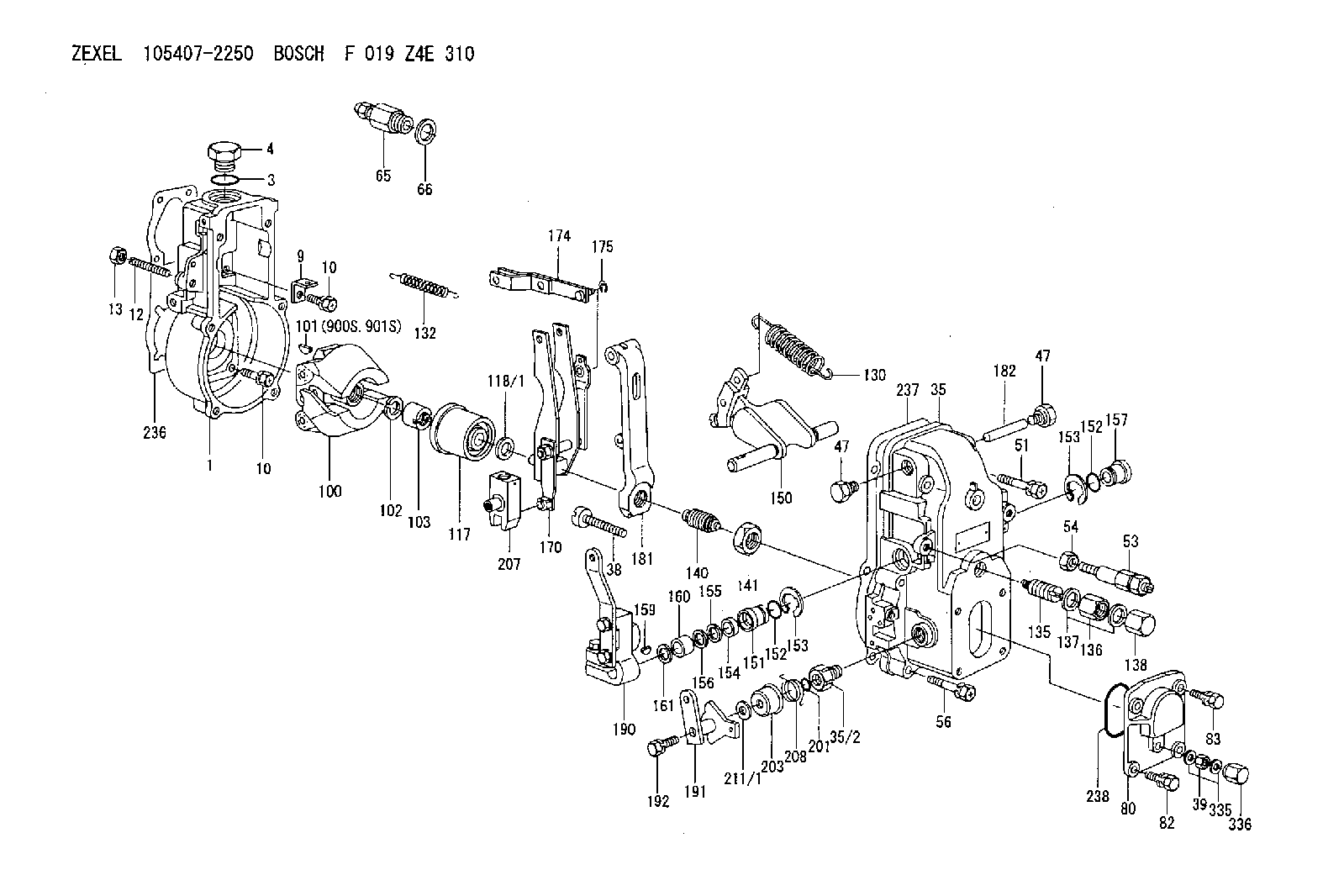
| 1. | [1] | 154000-4700 | GOVERNOR HOUSING |
| 3. | [1] | 029632-5070 | O-RING |
| 4. | [1] | 154007-2900 | CAPSULE |
| 9. | [1] | 154350-6000 | PLATE |
| 10. | [8] | 020106-2040 | BLEEDER SCREW M6P1L20 |
| 10. | [8] | 020106-2040 | BLEEDER SCREW M6P1L20 |
| 12. | [1] | 154010-1100 | FLAT-HEAD SCREW |
| 13. | [1] | 154011-0100 | HEXAGON NUT |
| 35. | [1] | 154500-7620 | GOVERNOR COVER |
| 35/2. | [1] | 154321-0400 | BUSHING |
| 38. | [1] | 154031-2400 | FLAT-HEAD SCREW |
| 39. | [1] | 139206-0600 | UNION NUT |
| 47. | [2] | 154036-0300 | CAPSULE |
| 47. | [2] | 154036-0300 | CAPSULE |
| 51. | [2] | 020106-5040 | BLEEDER SCREW |
| 53. | [1] | 154010-5220 | HEADLESS SCREW |
| 54. | [1] | 154011-1900 | UNION NUT |
| 56. | [4] | 020106-3840 | BLEEDER SCREW |
| 65. | [1] | 153021-5220 | STOPPING DEVICE |
| 66. | [1] | 026524-3040 | GASKET |
| 80. | [1] | 154063-1400 | COVER |
| 82. | [2] | 029020-6210 | BLEEDER SCREW |
| 83. | [2] | 020006-1640 | BLEEDER SCREW M6P1L16 4T |
| 100. | [1] | 154101-0020 | FLYWEIGHT ASSEMBLY |
| 101. | [1] | 025803-1310 | WOODRUFF KEY |
| 102. | [1] | 029321-2020 | LOCKING WASHER |
| 103. | [1] | 029231-2030 | UNION NUT |
| 117. | [1] | 154123-0120 | SLIDING PIECE |
| 118/1. | [0] | 029311-0010 | SHIM D14&10.1T0.2 |
| 118/1. | [0] | 029311-0180 | SHIM D14&10.1T0.3 |
| 118/1. | [0] | 029311-0190 | SHIM D14&10.1T0.40 |
| 118/1. | [0] | 029311-0210 | SHIM D14&10.1T1 |
| 118/1. | [0] | 139410-0000 | SHIM D14.0&10.1T0.5 |
| 118/1. | [0] | 139410-0100 | SHIM D14.0&10.1T1.5 |
| 118/1. | [0] | 139410-3000 | SHIM D14&10.1T2.0 |
| 118/1. | [0] | 139410-3100 | SHIM D14&10.1T3.0 |
| 118/1. | [0] | 139410-3200 | SHIM D14&10.1T4.0 |
| 130. | [1] | 154150-2700 | GOVERNOR SPRING |
| 132. | [1] | 154154-0500 | COILED SPRING |
| 135. | [1] | 154158-0820 | HEADLESS SCREW |
| 136. | [1] | 154011-2700 | UNION NUT |
| 137. | [2] | 026512-1540 | GASKET D15.4&12.2T1.50 |
| 138. | [1] | 154159-1200 | CAP NUT |
| 140. | [1] | 154185-2120 | HEADLESS SCREW |
| 141. | [1] | 029201-6010 | UNION NUT |
| 150. | [1] | 154200-7120 | SWIVELLING LEVER |
| 151. | [1] | 154204-4300 | BUSHING |
| 152. | [2] | 029631-8020 | O-RING |
| 152. | [2] | 029631-8020 | O-RING |
| 153. | [2] | 016010-1640 | LOCKING WASHER |
| 153. | [2] | 016010-1640 | LOCKING WASHER |
| 154. | [1] | 139611-0000 | PACKING RING |
| 155. | [1] | 139411-0000 | SHIM |
| 156. | [0] | 029311-1070 | SHIM D16&11T0.5 |
| 157. | [1] | 154204-4400 | BUSHING |
| 159. | [1] | 025803-1310 | WOODRUFF KEY |
| 160. | [1] | 154206-2800 | BUSHING |
| 161. | [0] | 154206-0200 | PLAIN WASHER D19.5&11.2T1.0 |
| 170. | [1] | 154210-2720 | FORK LEVER |
| 174. | [1] | 154230-2920 | STRAP |
| 175. | [1] | 016010-0540 | LOCKING WASHER |
| 181. | [1] | 154236-1500 | TENSIONING LEVER |
| 182. | [1] | 154237-0100 | BEARING PIN |
| 190. | [1] | 154343-3120 | CONTROL LEVER |
| 191. | [1] | 154307-5920 | CONTROL LEVER |
| 192. | [1] | 020006-3540 | BLEEDER SCREW |
| 201. | [1] | 029631-0030 | O-RING &9.8W2.3 |
| 203. | [1] | 154322-0100 | CAP |
| 207. | [1] | 154326-5020 | CONTROL LEVER |
| 208. | [1] | 154327-7600 | COILED SPRING |
| 211/1. | [0] | 029311-0520 | SHIM D20.8&10.3T0.2 |
| 211/1. | [0] | 029311-0530 | SHIM D20.8&10.3T0.25 |
| 211/1. | [0] | 029311-0540 | SHIM D20.8&10.3T0.3 |
| 211/1. | [0] | 029311-0550 | SHIM D20.8&10.3T0.35 |
| 211/1. | [0] | 029311-0560 | SHIM D20.8&10.3T0.4 |
| 211/1. | [0] | 029311-0570 | SHIM D20.8&10.3T0.5 |
| 236. | [1] | 154371-5600 | GASKET |
| 237. | [1] | 154390-0300 | GASKET |
| 238. | [1] | 029635-2020 | O-RING |
| 335. | [2] | 026506-1040 | GASKET D9.9&6.2T1 |
| 336. | [1] | 154035-1600 | CAP NUT |
| 900S. | [1] | 025803-1310 | WOODRUFF KEY |
| 901S. | [1] | 025803-1610 | WOODRUFF KEY |
Include in #1:
106672-3131
as GOVERNOR
Cross reference number
Zexel num
Bosch num
Firm num
Name
Information:
Locations and Methods for Measuring the Pressures of the Low-Pressure Fuel System
Illustration 1 g03325145
Front View of a typical fuel inlet lines group (A) Fuel inlet port (B) Test port for the fuel supply pressure (C) Fuel transfer pump (D) Test port location for system pressureInlet Fuel Pressure to the Transfer Pump (set at rated speed and load)
Install a 6V-3965 Fitting into Port (B) using a 214-7568 O-Ring Seal Note: The inlet pressure to the fuel transfer pump can affect overall system pressure. All filters or water separators before the transfer pump must be new and clean prior to setting the system pressure at the fuel pressure regulator.
Connect the 6V-7830 Pressure Gauge to the fitting installed in the previous step.
Set the engine to rated speed and load. Record the fuel pressure, and refer to the specifications above.Primary and Secondary Fuel Filter Differential Pressure
Primary and secondary fuel filter differential pressures are determined by the pressures from both sides of the fuel filters. This measurement will monitor fuel filter cleanliness and determine when the fuel filters require changing. Filter replacement will vary depending on fuel quality. Fuel quality can change with each shipment of fuel so monitoring the filter differential is necessary to obtain maximum filter life.Too high of a differential can cause air bubbles in the fuel system and if not corrected will lead to poor performance and injector damage. After the measurements are taken, refer to the specification above for the maximum allowable differential pressure.Primary filters or water separators should be properly sized to meet the flow requirements of the engine or engines as well as fuel being returned to the tank. Reference Table 4 for the flow requirements.
Table 4
3600 Engine Fuel Flow
Engine Model Rated Speed (rpm) Fuel Flow to Engine Fuel Flow from Engine Fuel Heat Rejection
3606 1000
41.5 L/min (11 US gpm)
32.4 L/min (8.6 US gpm)
12.5 kW (712 Btu/min)
900
38 L/min (10 US gpm)
30.0 L/min (7.9 US gpm)
11.0 kW (626 Btu/min)
750
31.5 L/min (8.3 US gpm)
24.5 L/min (6.5 US gpm)
10.5 kW (598 Btu/min)
720
30 L/min (7.9 US gpm)
23.6 L/min (6.2 US gpm)
10.0 kW (567 Btu/min)
3608 1000
41.5 L/min (11 US gpm)
30.0 L/min (7.9 US gpm)
16.7 kW (951 Btu/min)
900
38 L/min (10 US gpm)
27.6 L/min (7.3 US gpm)
14.6 kW (831 Btu/min)
750
31.5 L/min (8.3 US gpm)
22.6 L/min (6.0 US gpm)
14.0 kW (797 Btu/min)
720
30 L/min (7.9 US gpm)
21.4 L/min (5.6 US gpm)
13.3 kW (757 Btu/min)
3612 1000
78.5 L/min (20.7 US gpm)
60.1 L/min (15.9 US gpm)
25.0 kW (1423 Btu/min)
900
72 L/min (19 US gpm)
55.4 L/min (14.6 US gpm)
22.0 kW (1252 Btu/min)
750
61.2 L/min (16.2 US gpm)
47.3