Information governor
BOSCH
F 019 Z1E 580
f019z1e580
ZEXEL
105407-1740
1054071740
NISSAN-DIESEL
1910196574
1910196574
Rating:
Scheme ###:
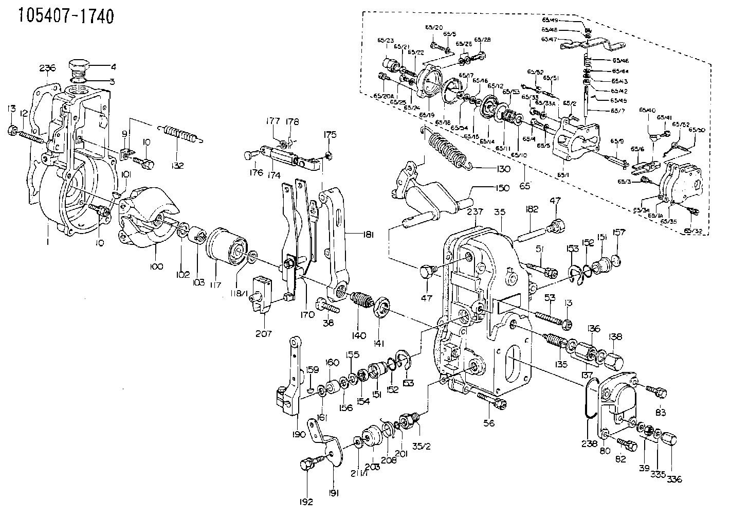
| 1. | [1] | 154000-4700 | GOVERNOR HOUSING |
| 3. | [1] | 029632-5070 | O-RING |
| 4. | [1] | 154007-2900 | CAPSULE |
| 9. | [1] | 154350-6000 | PLATE |
| 10. | [8] | 020106-2040 | BLEEDER SCREW |
| 10. | [8] | 020106-2040 | BLEEDER SCREW |
| 12. | [1] | 154010-0100 | FLAT-HEAD SCREW |
| 13. | [2] | 154011-0100 | HEXAGON NUT |
| 13. | [2] | 154011-0100 | HEXAGON NUT |
| 35. | [1] | 154500-1020 | GOVERNOR COVER |
| 35/2. | [1] | 154321-0400 | BUSHING |
| 38. | [1] | 154031-2400 | FLAT-HEAD SCREW |
| 39. | [1] | 139206-0600 | UNION NUT |
| 47. | [2] | 154036-0300 | CAPSULE |
| 47. | [2] | 154036-0300 | CAPSULE |
| 51. | [2] | 020106-5040 | BLEEDER SCREW |
| 53. | [1] | 154010-0200 | FLAT-HEAD SCREW |
| 56. | [4] | 020106-3840 | BLEEDER SCREW |
| 65. | [1] | 154407-8820 | MANIFOLD-PRESSURE COMP. |
| 65/1. | [1] | 154408-6120 | GOVERNOR HOUSING |
| 65/1A. | [1] | 154408-2400 | SPACER BUSHING |
| 65/1B. | [1] | 134009-0000 | SPACER BUSHING |
| 65/2. | [2] | 021006-2240 | FLAT-HEAD SCREW |
| 65/3. | [1] | 020006-1640 | BLEEDER SCREW |
| 65/4. | [1] | 029010-6220 | BLEEDER SCREW |
| 65/5. | [3] | 014110-6440 | LOCKING WASHER D12.2&6.1T1.5 |
| 65/5. | [3] | 014110-6440 | LOCKING WASHER D12.2&6.1T1.5 |
| 65/6. | [1] | 154408-1100 | CONTROL LEVER |
| 65/7. | [1] | 155004-2700 | LEVER SHAFT |
| 65/9. | [1] | 154400-4720 | STOP PIN |
| 65/10. | [0] | 029312-0180 | SHIM D25.5&20T0.5 |
| 65/10B. | [0] | 029312-0210 | SHIM D25.5&20T0.2 |
| 65/11. | [1] | 154402-2300 | COILED SPRING |
| 65/12. | [1] | 029300-8260 | PLAIN WASHER |
| 65/14. | [1] | 154400-0120 | DIAPHRAGM |
| 65/15. | [1] | 029310-8560 | SHIM |
| 65/16. | [1] | 139505-0000 | PLAIN WASHER |
| 65/17. | [1] | 013030-6040 | UNION NUT |
| 65/18. | [1] | 154404-3100 | PLATE |
| 65/19. | [1] | 154404-3700 | COVER |
| 65/20. | [2] | 029010-6310 | BLEEDER SCREW |
| 65/20A. | [1] | 020106-2240 | BLEEDER SCREW |
| 65/21. | [1] | 023040-6040 | UNION NUT |
| 65/22. | [1] | 154404-1100 | FLAT-HEAD SCREW |
| 65/23. | [1] | 154035-0320 | CAP NUT |
| 65/24. | [1] | 026506-1040 | GASKET |
| 65/25. | [1] | 029010-6010 | CAPSULE M6P1.0L7 |
| 65/26. | [2] | 026510-1340 | GASKET |
| 65/28. | [1] | 029731-0180 | EYE BOLT |
| 65/32. | [1] | 029020-6210 | BLEEDER SCREW |
| 65/33. | [1] | 029011-0120 | BLEEDER SCREW |
| 65/33A. | [1] | 026510-1340 | GASKET |
| 65/34. | [1] | 154390-0800 | GASKET |
| 65/35. | [1] | 154390-0900 | GASKET |
| 65/40. | [1] | 155003-1700 | CONTROL LEVER |
| 65/41. | [1] | 155006-0700 | BLEEDER SCREW |
| 65/42. | [1] | 139608-0000 | PACKING RING |
| 65/43. | [0] | 029310-8040 | SHIM D13.5&8T0.2 |
| 65/43. | [0] | 029310-8050 | SHIM D13.5&8T0.5 |
| 65/44. | [2] | 029300-8320 | SHIM |
| 65/45. | [1] | 025520-1210 | SPLIT PIN |
| 65/46. | [1] | 155005-1900 | COILED SPRING |
| 65/47. | [1] | 155400-1000 | CONTROL LEVER |
| 65/48. | [1] | 014110-8440 | LOCKING WASHER D15.4&8.2T2 |
| 65/49. | [1] | 013020-8140 | UNION NUT |
| 65/50. | [1] | 154037-2400 | FLAT-HEAD SCREW |
| 65/51. | [1] | 154037-0300 | FLAT-HEAD SCREW |
| 65/52. | [2] | 154038-0200 | HEXAGON NUT |
| 65/52. | [2] | 154038-0200 | HEXAGON NUT |
| 65/53. | [3] | 154413-2600 | GASKET |
| 65/54. | [1] | 139308-0700 | LOCKING WASHER |
| 80. | [1] | 154063-1400 | COVER |
| 82. | [2] | 029020-6210 | BLEEDER SCREW |
| 83. | [2] | 020006-1640 | BLEEDER SCREW |
| 100. | [1] | 154100-9720 | FLYWEIGHT ASSEMBLY |
| 101. | [1] | 025803-1310 | WOODRUFF KEY 13 MM |
| 102. | [1] | 029321-2020 | LOCKING WASHER |
| 103. | [1] | 029231-2030 | UNION NUT |
| 117. | [1] | 154123-0120 | SLIDING PIECE |
| 118/1. | [0] | 029311-0010 | SHIM D14&10.1T0.2 |
| 118/1. | [0] | 029311-0180 | SHIM D14&10.1T0.3 |
| 118/1. | [0] | 029311-0190 | SHIM D14&10.1T0.40 |
| 118/1. | [0] | 029311-0210 | SHIM D14&10.1T1 |
| 118/1. | [0] | 139410-0000 | SHIM D14&10.1T0.5 |
| 118/1. | [0] | 139410-0100 | SHIM D14&10.1T1.5 |
| 118/1. | [0] | 139410-3000 | SHIM D14&10.1T2.0 |
| 118/1. | [0] | 139410-3100 | SHIM D14&10.1T3.0 |
| 118/1. | [0] | 139410-3200 | SHIM D14&10.1T4.0 |
| 130. | [1] | 154150-0400 | GOVERNOR SPRING |
| 132. | [1] | 154154-0800 | COILED SPRING |
| 135. | [1] | 154158-0820 | HEADLESS SCREW |
| 136. | [1] | 154011-1700 | UNION NUT |
| 137. | [2] | 026512-1540 | GASKET |
| 138. | [1] | 154159-1200 | CAP NUT |
| 140. | [1] | 154185-1320 | HEADLESS SCREW |
| 141. | [1] | 029201-6010 | UNION NUT |
| 150. | [1] | 154200-7020 | SWIVELLING LEVER |
| 151. | [1] | 154204-4300 | BUSHING |
| 151. | [1] | 154204-4300 | BUSHING |
| 152. | [2] | 029631-8020 | O-RING |
| 152. | [2] | 029631-8020 | O-RING |
| 153. | [2] | 016010-1640 | LOCKING WASHER |
| 153. | [2] | 016010-1640 | LOCKING WASHER |
| 154. | [1] | 139611-0000 | PACKING RING |
| 155. | [1] | 139411-0000 | SHIM |
| 156. | [0] | 029311-1070 | SHIM D16&11T0.5 |
| 157. | [1] | 154204-4400 | BUSHING |
| 159. | [1] | 025803-1310 | WOODRUFF KEY 13 MM |
| 160. | [1] | 154206-2800 | BUSHING |
| 161. | [0] | 154206-0200 | PLAIN WASHER D19.5&11.2T1.0 |
| 170. | [1] | 154210-9920 | FORK LEVER |
| 174. | [1] | 154230-5120 | STRAP |
| 175. | [1] | 016010-0540 | LOCKING WASHER |
| 176. | [1] | 159231-4900 | BEARING PIN |
| 178. | [1] | 155402-3800 | SAFETY PIN |
| 181. | [1] | 154236-4100 | TENSIONING LEVER |
| 182. | [1] | 154237-0100 | BEARING PIN |
| 190. | [1] | 154309-6120 | CONTROL LEVER |
| 191. | [1] | 154304-7100 | CONTROL LEVER |
| 192. | [1] | 020006-1640 | BLEEDER SCREW |
| 201. | [1] | 029631-0030 | O-RING |
| 203. | [1] | 154322-0100 | CAP |
| 207. | [1] | 154326-5020 | CONTROL LEVER |
| 208. | [1] | 154327-7600 | COILED SPRING |
| 211/1. | [0] | 029311-0520 | SHIM D20.8&10.3T0.2 |
| 211/1. | [0] | 029311-0530 | SHIM D20.8&10.3T0.25 |
| 211/1. | [0] | 029311-0540 | SHIM D20.8&10.3T0.3 |
| 211/1. | [0] | 029311-0550 | SHIM D20.8&10.3T0.35 |
| 211/1. | [0] | 029311-0560 | SHIM D20.8&10.3T0.4 |
| 211/1. | [0] | 029311-0570 | SHIM D20.8&10.3T0.5 |
| 236. | [1] | 154371-5600 | GASKET |
| 237. | [1] | 154390-0300 | GASKET |
| 238. | [1] | 029635-2020 | O-RING |
| 335. | [2] | 026506-1040 | GASKET |
| 336. | [1] | 154035-1600 | CAP NUT |
| 900S. | [1] | 025803-1310 | WOODRUFF KEY 13 MM |
| 901S. | [1] | 025803-1610 | WOODRUFF KEY 16 MM |
Cross reference number
Zexel num
Bosch num
Firm num
Name
1910196574 NISSAN-DIESEL
GOVERNOR
K 14JB MECHANICAL GOVERNOR GOV RSV GOV
K 14JB MECHANICAL GOVERNOR GOV RSV GOV
Information:
Important Safety Information
Illustration 1 g02139237Work safely. Most accidents that involve product operation, maintenance, and repair are caused by failure to observe basic safety rules or precautions. An accident can often be avoided by recognizing potentially hazardous situations before an accident occurs. A person must be alert to potential hazards. This person should also have the necessary training, skills, and tools to perform these functions properly. Safety precautions and warnings are provided in this instruction and on the product. If these hazard warnings are not heeded, bodily injury or death could occur to you or to other persons. Caterpillar cannot anticipate every possible circumstance that might involve a potential hazard. Therefore, the warnings in this publication and the warnings that are on the product are not all inclusive. If a tool, a procedure, a work method, or operating technique that is not recommended by Caterpillar is used, ensure that it is safe for you and for other people to use. Ensure that the product will not be damaged or the product will not be made unsafe by the operation, lubrication, maintenance, or the repair procedures that are used.
Improper operation, lubrication, maintenance or repair of this product can be dangerous and could result in injury or death.Do not operate or perform any lubrication, maintenance or repair on this product, until you have read and understood the operation, lubrication, maintenance and repair information.
Safety precautions and warnings are provided in this manual and on the product. If these hazard warnings are not heeded, bodily injury or death could occur to you or to other persons.The hazards are identified by the safety alert symbol which is followed by a signal word such as danger, warning, or caution. The "" safety alert symbol is shown below.
Illustration 2 g00008666This safety alert symbol means:Pay attention!Become alert!Your safety is involved.The message that appears under the safety alert symbol explains the hazard.Operations that may cause product damage are identified by "" labels on the product and in this publication.Caterpillar cannot anticipate every possible circumstance that might involve a potential hazard. The safety information in this document and the safety information on the machine are not all inclusive. Determine that the tools, procedures, work methods, and operating techniques are safe. Determine that the operation, lubrication, maintenance, and repair procedures will not damage the machine. Also, you must determine that the operation, lubrication, maintenance, and repair procedures will not make the machine unsafe.The information, the specifications, and the illustrations that exist in this guideline are based on information which was available at the time of publication. The specifications, torques, pressures, measurements, adjustments, illustrations, and other items can change at any time. These changes can affect the service that is given to the product. Obtain the complete, most current information before you start any job. Caterpillar dealers can supply the most current information.Summary
The information included in this guideline should serve as an aid in fuel injection pump housing test procedure.Service Letters and Technical Information Bulletins
The most recent Service Letters and Technical Information Bulletins