Information governor
BOSCH
F 019 Z4E 293
f019z4e293
ZEXEL
105407-1390
1054071390
HINO
223201361A
223201361a
Rating:
Scheme ###:
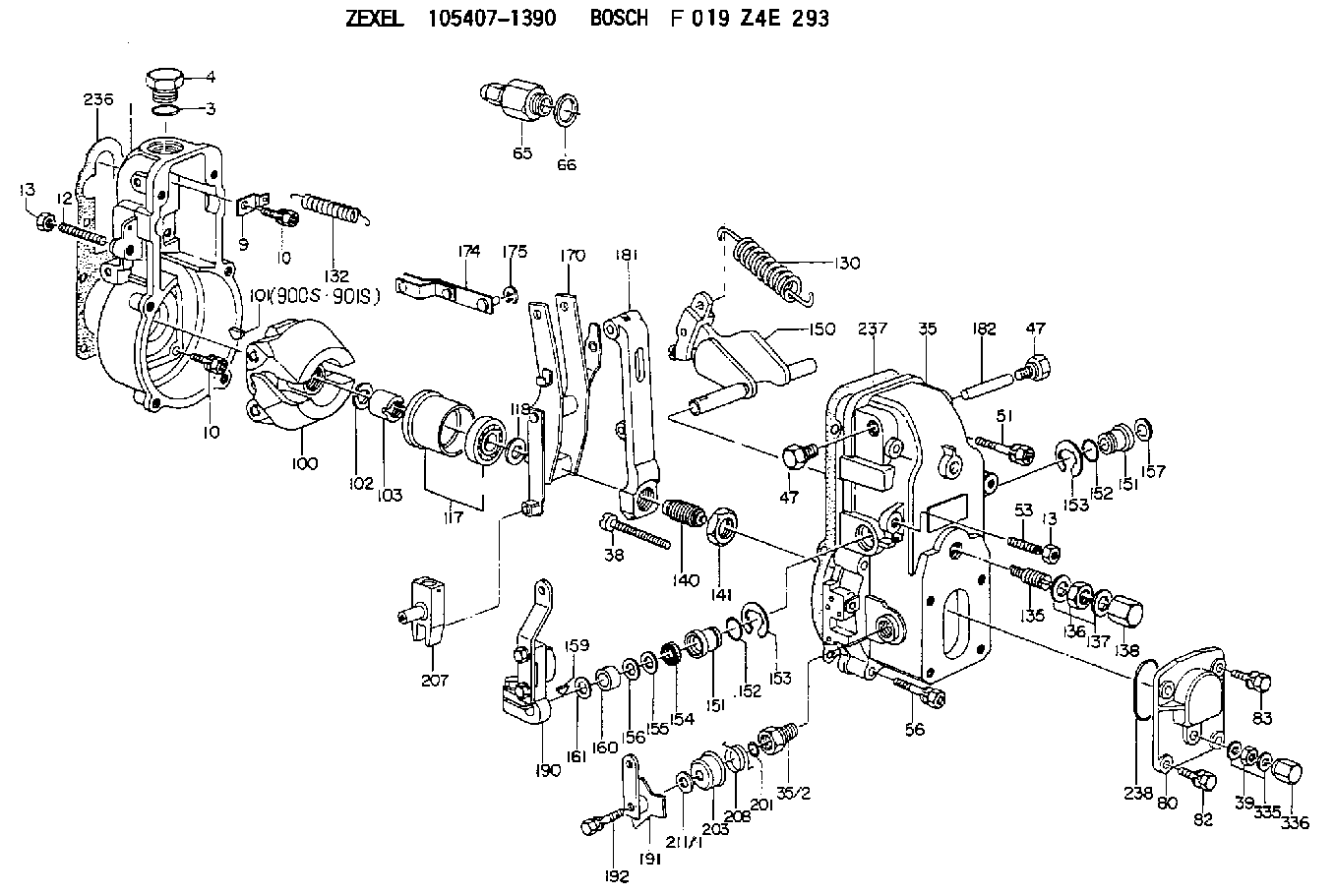
| 1. | [1] | 154000-4700 | GOVERNOR HOUSING |
| 3. | [1] | 029632-5070 | O-RING |
| 4. | [1] | 154007-2900 | CAPSULE |
| 9. | [1] | 154350-6000 | PLATE |
| 10. | [8] | 020106-2040 | BLEEDER SCREW |
| 10. | [8] | 020106-2040 | BLEEDER SCREW |
| 12. | [1] | 154010-1100 | FLAT-HEAD SCREW |
| 13. | [2] | 154011-0100 | HEXAGON NUT |
| 13. | [2] | 154011-0100 | HEXAGON NUT |
| 35. | [1] | 154500-1020 | GOVERNOR COVER |
| 35/2. | [1] | 154321-0400 | BUSHING |
| 38. | [1] | 154031-2400 | FLAT-HEAD SCREW |
| 39. | [1] | 139206-0600 | UNION NUT |
| 47. | [2] | 154036-0300 | CAPSULE |
| 47. | [2] | 154036-0300 | CAPSULE |
| 51. | [2] | 020106-5040 | BLEEDER SCREW |
| 53. | [1] | 154010-0100 | FLAT-HEAD SCREW |
| 56. | [4] | 020106-3840 | BLEEDER SCREW |
| 65. | [1] | 155404-3400 | CAP |
| 66. | [1] | 026524-3040 | GASKET |
| 80. | [1] | 154063-1400 | COVER |
| 82. | [2] | 029020-6210 | BLEEDER SCREW |
| 83. | [2] | 020006-1640 | BLEEDER SCREW |
| 100. | [1] | 154101-0120 | FLYWEIGHT |
| 101. | [1] | 025803-1310 | WOODRUFF KEY 13 MM |
| 102. | [1] | 029321-2020 | LOCKING WASHER |
| 103. | [1] | 029231-2030 | UNION NUT |
| 117. | [1] | 154123-0120 | SLIDING PIECE |
| 118/1. | [0] | 029311-0010 | SHIM D14&10.1T0.2 |
| 118/1. | [0] | 029311-0180 | SHIM D14&10.1T0.3 |
| 118/1. | [0] | 029311-0190 | SHIM D14&10.1T0.40 |
| 118/1. | [0] | 029311-0210 | SHIM D14&10.1T1 |
| 118/1. | [0] | 139410-0000 | SHIM D14&10.1T0.5 |
| 118/1. | [0] | 139410-0100 | SHIM D14&10.1T1.5 |
| 118/1. | [0] | 139410-3000 | SHIM D14&10.1T2.0 |
| 118/1. | [0] | 139410-3100 | SHIM D14&10.1T3.0 |
| 118/1. | [0] | 139410-3200 | SHIM D14&10.1T4.0 |
| 130. | [1] | 154150-0400 | GOVERNOR SPRING |
| 132. | [1] | 154154-0500 | COILED SPRING |
| 135. | [1] | 154158-1320 | HEADLESS SCREW |
| 136. | [1] | 154011-1700 | UNION NUT |
| 137. | [2] | 026512-1540 | GASKET |
| 138. | [1] | 154159-1200 | CAP NUT |
| 140. | [1] | 154185-1320 | HEADLESS SCREW |
| 141. | [1] | 029201-6010 | UNION NUT |
| 150. | [1] | 154200-7020 | SWIVELLING LEVER |
| 151. | [1] | 154204-4300 | BUSHING |
| 151. | [1] | 154204-4300 | BUSHING |
| 152. | [2] | 029631-8020 | O-RING |
| 152. | [2] | 029631-8020 | O-RING |
| 153. | [2] | 016010-1640 | LOCKING WASHER |
| 153. | [2] | 016010-1640 | LOCKING WASHER |
| 154. | [1] | 139611-0000 | PACKING RING |
| 155. | [1] | 139411-0000 | SHIM |
| 156. | [0] | 029311-1070 | SHIM D16&11T0.5 |
| 157. | [1] | 154204-4400 | BUSHING |
| 159. | [1] | 025803-1310 | WOODRUFF KEY 13 MM |
| 160. | [1] | 154206-2800 | BUSHING |
| 161. | [0] | 154206-0200 | PLAIN WASHER D19.5&11.2T1.0 |
| 170. | [1] | 154210-9920 | FORK LEVER |
| 174. | [1] | 154230-2920 | STRAP |
| 175. | [1] | 016010-0540 | LOCKING WASHER |
| 181. | [1] | 154236-4100 | TENSIONING LEVER |
| 182. | [1] | 154237-0100 | BEARING PIN |
| 190. | [1] | 154341-8120 | CONTROL LEVER |
| 191. | [1] | 154307-5920 | CONTROL LEVER |
| 192. | [1] | 020006-3540 | BLEEDER SCREW |
| 201. | [1] | 029631-0030 | O-RING |
| 203. | [1] | 154322-0100 | CAP |
| 207. | [1] | 154326-5020 | CONTROL LEVER |
| 208. | [1] | 154327-7600 | COILED SPRING |
| 211/1. | [0] | 029311-0520 | SHIM D20.8&10.3T0.2 |
| 211/1. | [0] | 029311-0530 | SHIM D20.8&10.3T0.25 |
| 211/1. | [0] | 029311-0540 | SHIM D20.8&10.3T0.3 |
| 211/1. | [0] | 029311-0550 | SHIM D20.8&10.3T0.35 |
| 211/1. | [0] | 029311-0560 | SHIM D20.8&10.3T0.4 |
| 211/1. | [0] | 029311-0570 | SHIM D20.8&10.3T0.5 |
| 236. | [1] | 154371-5600 | GASKET |
| 237. | [1] | 154390-0300 | GASKET |
| 238. | [1] | 029635-2020 | O-RING |
| 335. | [2] | 026506-1040 | GASKET |
| 336. | [1] | 154035-1600 | CAP NUT |
| 900S. | [1] | 025803-1310 | WOODRUFF KEY 13 MM |
| 901S. | [1] | 025803-1610 | WOODRUFF KEY 16 MM |
Include in #1:
106691-3032
as GOVERNOR
Cross reference number
Zexel num
Bosch num
Firm num
Name
Information:
Introduction
Do not perform any procedure in this Special Instruction until you read this information and you understand this information.Certain engine components may need to be cleaned if soot is found in the system beyond the Diesel Particulate Filter (DPF). The contaminated components can be cleaned with hot water and soap by hand washing or in a parts washer. Do not use solvents. Special care must be taken with handling components of the Clean Gas Induction (CGI) cooler.Safety Section
Sulfuric Acid Burn Hazard, may cause serious personal injury.The clean gas induction cooler may contain a small amount of sulfuric acid. The use of fuel with sulfur levels greater than 15 ppm may increase the amount of sulfuric acid formed. The sulfuric acid may spill from the CGI cooler during service of the engine and may travel to other downstream components. The sulfuric acid will burn the eyes, skin and clothing on contact. Always wear the appropriate personal protective equipment (PPE) that is noted on a material safety data sheet (MSDS) for sulfuric acid. Always follow the directions for first aid that are noted on a material safety data sheet (MSDS) for sulfuric acid.
Hot engine components can cause injury from burns. Before performing maintenance on the engine, allow the engine and the components to cool.
Wear goggles, gloves, protective clothing, and a National Institute for Occupational Safety and Health (NIOSH) approved P95 or N95 half-face respirator when handling a used Diesel Particulate Filter or Catalytic Converter Muffler. Failure to do so could result in personal injury.
Care must be taken to ensure that fluids are contained during performance of inspection, maintenance, testing, adjusting and repair of the product. Be prepared to collect the fluid with suitable containers before opening any compartment or disassembling any component containing fluids.Refer to Special Publication, NENG2500, "Caterpillar Dealer Service Tool Catalog" for tools and supplies suitable to collect and contain fluids on Caterpillar products.Dispose of all fluids according to local regulations and mandates.
Required Tools
Table 1
Part Number Part Description Qty
9N-6379 Air Cleaner Adapter Boot 1
4P-2706 Protection Cap 1 Cleaning Procedure
Start at the DPF outlet and inspect the components downstream of the CGI pipe until excessive soot is no longer found. If necessary, clean these components .
If soot is found at the entrance to the CGI cooler, remove the CGI cooler from the engine. Refer to Disassembly and Assembly, RENR9706, "Clean Gas Induction Cooler - Remove and Install", "Removal Procedure" in order to properly remove the CGI cooler.
After removing the CGI cooler, immediately submerge the CGI cooler into the hot soapy water.
Remove the 9N-6379 Air Cleaner Adapter Boot and the 4P-2706 Protection Cap from the ends of the CGI cooler.
Allow the water to circulate through the CGI cooler in order to dilute any sulfuric acid that may be present. Clean out the soot.
Continue to inspect the following components downstream of the CGI cooler until excessive soot is no longer found: the CGI mixing valve, the