Information governor
BOSCH
F 019 Z1E 823
f019z1e823
ZEXEL
105407-1080
1054071080
Rating:
Scheme ###:
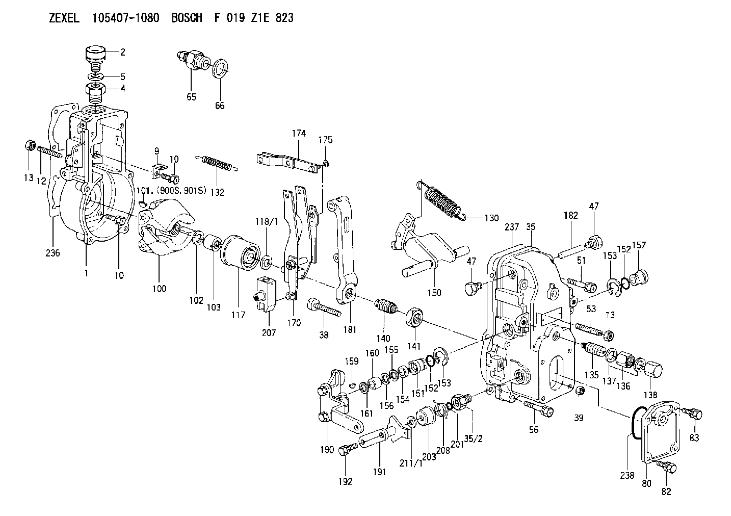
| 1. | [1] | 154000-4700 | GOVERNOR HOUSING |
| 2. | [1] | 155406-5820 | AIR FILTER |
| 4. | [1] | 154007-2600 | ADAPTOR |
| 5. | [1] | 026512-1540 | GASKET D15.4&12.2T1.50 |
| 9. | [1] | 154350-6000 | PLATE |
| 10. | [8] | 020106-2040 | BLEEDER SCREW M6P1L20 |
| 10. | [8] | 020106-2040 | BLEEDER SCREW M6P1L20 |
| 12. | [1] | 154010-0500 | FLAT-HEAD SCREW |
| 13. | [2] | 154011-0100 | HEXAGON NUT |
| 13. | [2] | 154011-0100 | HEXAGON NUT |
| 35. | [1] | 154500-1020 | GOVERNOR COVER |
| 35/2. | [1] | 154321-0400 | BUSHING |
| 38. | [1] | 154031-0100 | FLAT-HEAD SCREW |
| 39. | [1] | 013020-6020 | UNION NUT M6P1H5 |
| 47. | [2] | 154036-0300 | CAPSULE |
| 47. | [2] | 154036-0300 | CAPSULE |
| 51. | [2] | 020106-5040 | BLEEDER SCREW |
| 53. | [1] | 154010-0100 | FLAT-HEAD SCREW |
| 56. | [4] | 020106-3840 | BLEEDER SCREW |
| 65. | [1] | 153021-8320 | STOPPING DEVICE |
| 66. | [1] | 026524-3040 | GASKET |
| 80. | [1] | 154060-4900 | COVER |
| 82. | [2] | 029020-6210 | BLEEDER SCREW |
| 83. | [2] | 020006-1640 | BLEEDER SCREW M6P1L16 4T |
| 100. | [1] | 154100-2320 | FLYWEIGHT ASSEMBLY |
| 101. | [1] | 025803-1310 | WOODRUFF KEY |
| 102. | [1] | 029321-2020 | LOCKING WASHER |
| 103. | [1] | 029231-2030 | UNION NUT |
| 117. | [1] | 154123-0120 | SLIDING PIECE |
| 118/1. | [0] | 029311-0010 | SHIM D14&10.1T0.2 |
| 118/1. | [0] | 029311-0180 | SHIM D14&10.1T0.3 |
| 118/1. | [0] | 029311-0190 | SHIM D14&10.1T0.40 |
| 118/1. | [0] | 029311-0210 | SHIM D14&10.1T1 |
| 118/1. | [0] | 139410-0000 | SHIM D14.0&10.1T0.5 |
| 118/1. | [0] | 139410-0100 | SHIM D14.0&10.1T1.5 |
| 118/1. | [0] | 139410-3000 | SHIM D14&10.1T2.0 |
| 118/1. | [0] | 139410-3100 | SHIM D14&10.1T3.0 |
| 118/1. | [0] | 139410-3200 | SHIM D14&10.1T4.0 |
| 130. | [1] | 154150-0300 | GOVERNOR SPRING |
| 132. | [1] | 154154-0800 | COILED SPRING |
| 135. | [1] | 154157-0320 | HEADLESS SCREW |
| 136. | [1] | 029201-2030 | UNION NUT M12P1.0H4 |
| 137. | [2] | 026512-1540 | GASKET D15.4&12.2T1.50 |
| 138. | [1] | 154159-1200 | CAP NUT |
| 140. | [1] | 154185-1320 | HEADLESS SCREW |
| 141. | [1] | 029201-6010 | UNION NUT |
| 150. | [1] | 154200-7020 | SWIVELLING LEVER |
| 151. | [1] | 154204-4300 | BUSHING |
| 152. | [2] | 029631-8020 | O-RING |
| 152. | [2] | 029631-8020 | O-RING |
| 153. | [2] | 016010-1640 | LOCKING WASHER |
| 153. | [2] | 016010-1640 | LOCKING WASHER |
| 154. | [1] | 139611-0000 | PACKING RING |
| 155. | [1] | 139411-0000 | SHIM |
| 156. | [0] | 029311-1070 | SHIM D16&11T0.5 |
| 157. | [1] | 154204-4400 | BUSHING |
| 159. | [1] | 025803-1310 | WOODRUFF KEY |
| 160. | [1] | 154206-2800 | BUSHING |
| 161. | [0] | 154206-0200 | PLAIN WASHER D19.5&11.2T1.0 |
| 170. | [1] | 154210-9920 | FORK LEVER |
| 174. | [1] | 154230-2920 | STRAP |
| 175. | [1] | 016010-0540 | LOCKING WASHER |
| 181. | [1] | 154236-4100 | TENSIONING LEVER |
| 182. | [1] | 154237-0100 | BEARING PIN |
| 190. | [1] | 154341-5620 | CONTROL LEVER |
| 191. | [1] | 154304-4820 | CONTROL LEVER |
| 192. | [1] | 020006-4540 | BLEEDER SCREW M6P1L45 |
| 201. | [1] | 029631-0030 | O-RING &9.8W2.3 |
| 203. | [1] | 154322-0100 | CAP |
| 207. | [1] | 154326-5020 | CONTROL LEVER |
| 208. | [1] | 154327-7600 | COILED SPRING |
| 211/1. | [0] | 029311-0520 | SHIM D20.8&10.3T0.2 |
| 211/1. | [0] | 029311-0530 | SHIM D20.8&10.3T0.25 |
| 211/1. | [0] | 029311-0540 | SHIM D20.8&10.3T0.3 |
| 211/1. | [0] | 029311-0550 | SHIM D20.8&10.3T0.35 |
| 211/1. | [0] | 029311-0560 | SHIM D20.8&10.3T0.4 |
| 211/1. | [0] | 029311-0570 | SHIM D20.8&10.3T0.5 |
| 236. | [1] | 154371-5600 | GASKET |
| 237. | [1] | 154390-0300 | GASKET |
| 238. | [1] | 029635-2020 | O-RING |
| 900S. | [1] | 025803-1310 | WOODRUFF KEY |
| 901S. | [1] | 025803-1610 | WOODRUFF KEY |
Cross reference number
Zexel num
Bosch num
Firm num
Name
105407-1080
GOVERNOR
K 14JB MECHANICAL GOVERNOR GOV RSV GOV
K 14JB MECHANICAL GOVERNOR GOV RSV GOV
Information:
Illustration 21 shows the direction the rack moves when the fuel injector is receiving fuel.
Illustration 22 g01455811
Illustration 1 - Flowchart for the Air in Fuel Test (Test F)
Illustration 23 g01455812
Illustration 2 - Flowchart for the Air in Fuel Test (Test F)Fuel Injector Cranking Test (Test G)
Note: The fuel injector cranking test checks for worn out injectors by measuring the cranking rack.
Illustration 24 g01412134
(3) The rack control (4) The number one fuel injectorNote: Refer to Illustration 24 for the location of the rack control and the location of the number one injector.
Illustration 25 g01412115
Flowchart for the Fuel Injector Cranking Test (Test G)Fuel Shutoff Solenoid Test (Test H)
Note: The fuel shutoff solenoid test determines if the fuel shutoff solenoid and wiring harness are operating properly.
Illustration 26 g01412143
Flowchart for the Fuel Shutoff Solenoid Test (Test H)Fuel Ratio Control (FRC) Setting Test (Test I)
Note: The FRC setting test checks the FRC setting.
Illustration 27 g01412145
Flowchart for the Fuel Ratio Control (FRC) Setting Test (Test I)Governor Servo Retaining Ring Test (Test J)
Note: Do not run the engine during this test.Note: The governor servo retaining ring test checks for faulty internal parts of the governor.
Illustration 28 g01422811
(1) Paddle
Illustration 29 g01422821
(2) Clevis pin
Illustration 30 g01412147
Flowchart for the Governor Servo Retaining Ring Test (Test J)Fuel Transfer Pump Test (Test K)
Note: The fuel transfer pump test is a visual inspection of the fuel transfer pump components.
Illustration 31 g01412150
(1) Screen (2) Inlet check valve (3) Spring (4) Bolt (5) Piston (6) Outlet check valve (7) Freeze plug (8) Piston check valve (9) Passage (10) Tappet Assembly (11) CamNote: Refer to Illustration 31 for the location of the components for the fuel transfer pump.
Illustration 32 g01412149
Flowchart for the Fuel Transfer Pump Test (Test K)Fuel Ratio Control (FRC) Diaphragm Leak Test (Test L)
Note: The FRC diaphragm leak test checks for a leaking FRC diaphragm.
Illustration 33 g01412154
Flowchart for the Fuel Ratio Control (FRC) Diaphragm Leak Test (Test L)