Information governor
BOSCH
F 01G 29N 0ED
f01g29n0ed
ZEXEL
105404-6220
1054046220
Rating:
Scheme ###:
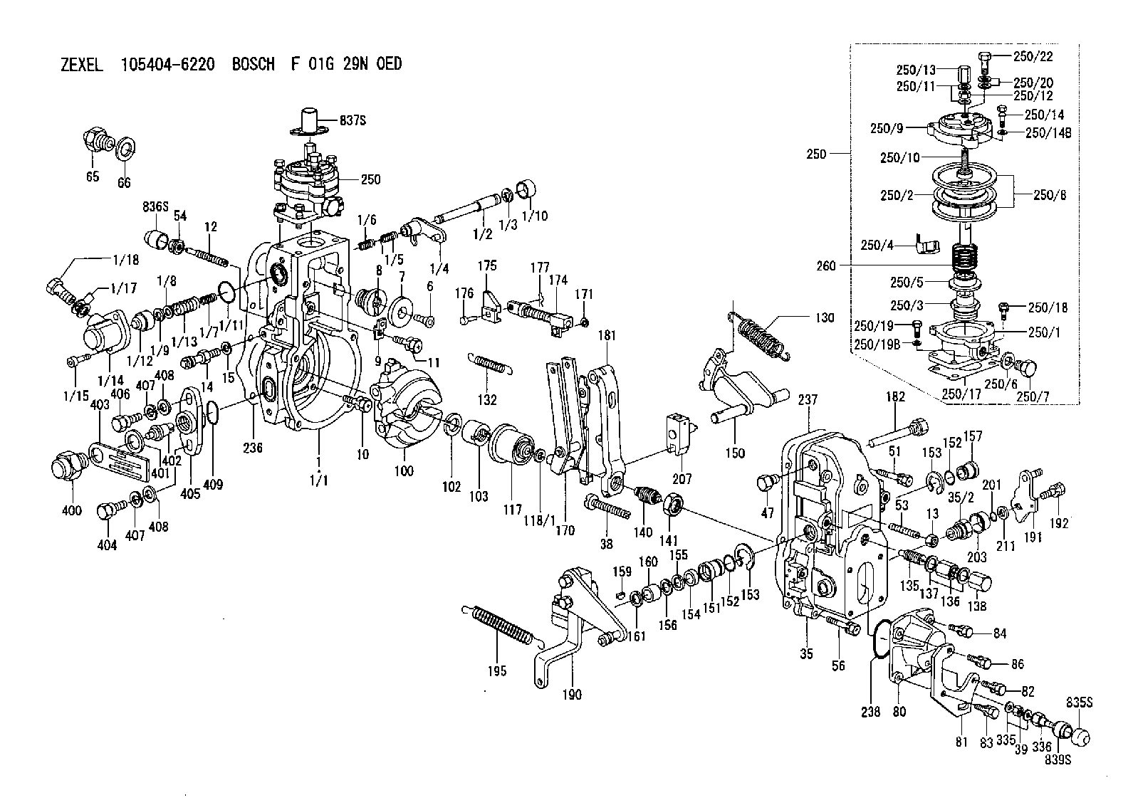
| 1. | [1] | 154620-0820 | GOVERNOR HOUSING |
| 1/1. | [1] | 154620-0020 | GOVERNOR HOUSING |
| 1/2. | [1] | 154621-3701 | LEVER SHAFT |
| 1/3. | [1] | 016010-0740 | LOCKING WASHER |
| 1/4. | [1] | 154415-3320 | CONTROL LEVER |
| 1/5. | [1] | 154415-3400 | COILED SPRING |
| 1/6. | [1] | 154621-3800 | COILED SPRING |
| 1/7. | [1] | 154621-4400 | COILED SPRING |
| 1/8. | [1] | 139406-1400 | SHIM |
| 1/9. | [1] | 016010-0540 | LOCKING WASHER |
| 1/10. | [1] | 154621-3600 | CAP |
| 1/11. | [1] | 016520-2210 | O-RING |
| 1/12. | [1] | 154621-3500 | BUSHING |
| 1/13. | [1] | 154621-3900 | COILED SPRING |
| 1/14. | [1] | 154620-1600 | COVER |
| 1/15. | [2] | 010235-1640 | HEX-SOCKET-HEAD CAP SCREW |
| 1/17. | [2] | 029341-0110 | GASKET |
| 1/18. | [1] | 029731-0120 | EYE BOLT |
| 6. | [1] | 154621-4300 | BLEEDER SCREW |
| 7. | [1] | 154621-4100 | PLAIN WASHER |
| 8. | [1] | 154620-7900 | ADAPTOR |
| 9. | [1] | 154375-9020 | PLATE |
| 10. | [5] | 029010-6810 | BLEEDER SCREW |
| 11. | [1] | 020106-1840 | BLEEDER SCREW |
| 12. | [1] | 154013-5000 | FLAT-HEAD SCREW L67.L51M8P1.25 |
| 13. | [1] | 154011-0100 | HEXAGON NUT |
| 14. | [1] | 154013-2320 | BLEEDER SCREW |
| 15. | [1] | 014110-8440 | LOCKING WASHER D15.4&8.2T2 |
| 35. | [1] | 154500-3020 | GOVERNOR COVER |
| 35/2. | [1] | 154321-0400 | BUSHING |
| 38. | [1] | 154031-3000 | FLAT-HEAD SCREW |
| 39. | [1] | 139206-0600 | UNION NUT |
| 47. | [1] | 154036-0300 | CAPSULE |
| 51. | [2] | 139006-7100 | BLEEDER SCREW |
| 53. | [1] | 154010-0200 | FLAT-HEAD SCREW |
| 54. | [1] | 154011-4900 | UNION NUT |
| 56. | [4] | 020106-3840 | BLEEDER SCREW |
| 65. | [1] | 155404-3500 | CAP |
| 66. | [1] | 026518-2240 | GASKET |
| 80. | [1] | 154063-5100 | COVER |
| 81. | [1] | 154358-7200 | BRACKET |
| 82. | [1] | 020006-2040 | BLEEDER SCREW |
| 83. | [1] | 020006-2040 | BLEEDER SCREW |
| 84. | [1] | 020006-1640 | BLEEDER SCREW |
| 86. | [1] | 020006-2040 | BLEEDER SCREW |
| 100. | [1] | 154621-2120 | FLYWEIGHT ASSEMBLY |
| 102. | [1] | 029321-2020 | LOCKING WASHER |
| 103. | [1] | 029231-2030 | UNION NUT |
| 117. | [1] | 154123-0120 | SLIDING PIECE |
| 118/1. | [0] | 029311-0010 | SHIM D14&10.1T0.2 |
| 118/1. | [0] | 029311-0180 | SHIM D14&10.1T0.3 |
| 118/1. | [0] | 029311-0190 | SHIM D14&10.1T0.40 |
| 118/1. | [0] | 029311-0210 | SHIM D14&10.1T1 |
| 118/1. | [0] | 139410-0000 | SHIM D14&10.1T0.5 |
| 118/1. | [0] | 139410-0100 | SHIM D14&10.1T1.5 |
| 118/1. | [0] | 139410-3000 | SHIM D14&10.1T2.0 |
| 118/1. | [0] | 139410-3100 | SHIM D14&10.1T3.0 |
| 118/1. | [0] | 139410-3200 | SHIM D14&10.1T4.0 |
| 130. | [1] | 154150-6400 | GOVERNOR SPRING |
| 132. | [1] | 154154-5200 | COILED SPRING |
| 135. | [1] | 154158-1720 | HEADLESS SCREW |
| 136. | [1] | 154011-1700 | UNION NUT |
| 137. | [2] | 026512-1540 | GASKET |
| 138. | [1] | 154159-1200 | CAP NUT |
| 140. | [1] | 154177-1020 | HEADLESS SCREW |
| 141. | [1] | 029201-6010 | UNION NUT |
| 150. | [1] | 154200-7020 | SWIVELLING LEVER |
| 151. | [1] | 154204-4300 | BUSHING |
| 152. | [2] | 029631-8020 | O-RING |
| 152. | [2] | 029631-8020 | O-RING |
| 153. | [2] | 016010-1640 | LOCKING WASHER |
| 153. | [2] | 016010-1640 | LOCKING WASHER |
| 154. | [1] | 139611-0000 | PACKING RING |
| 155. | [1] | 139411-0000 | SHIM |
| 156. | [0] | 029311-1070 | SHIM D16&11T0.5 |
| 157. | [1] | 154204-4400 | BUSHING |
| 159. | [1] | 025803-1310 | WOODRUFF KEY 13 MM |
| 160. | [1] | 154206-2800 | BUSHING |
| 161. | [0] | 154206-0200 | PLAIN WASHER D19.5&11.2T1.0 |
| 170. | [1] | 154218-1620 | FORK LEVER |
| 171. | [1] | 016010-0540 | LOCKING WASHER |
| 174. | [1] | 154235-4720 | STRAP |
| 175. | [1] | 154232-3200 | CONNECTOR |
| 176. | [1] | 154222-5800 | BEARING PIN |
| 177. | [1] | 155402-3800 | SAFETY PIN |
| 181. | [1] | 154236-4100 | TENSIONING LEVER |
| 182. | [1] | 154237-1100 | BEARING PIN |
| 190. | [1] | 154395-8420 | CONTROL LEVER |
| 191. | [1] | 154382-3720 | CONTROL LEVER |
| 192. | [1] | 020006-1840 | BLEEDER SCREW |
| 195. | [1] | 154314-2500 | COILED SPRING |
| 201. | [1] | 029631-0030 | O-RING |
| 203. | [1] | 154322-0600 | CAP |
| 207. | [1] | 154326-5120 | CONTROL LEVER |
| 211. | [0] | 029311-0220 | SHIM D18&10.3T0.2 |
| 211B. | [0] | 029311-0230 | SHIM D18&10.3T0.5 |
| 236. | [1] | 154390-0000 | GASKET |
| 237. | [1] | 154390-0300 | GASKET |
| 238. | [1] | 029635-2020 | O-RING |
| 250. | [1] | 154422-7820 | MANIFOLD-PRESSURE COMP. |
| 250. | [1] | 154422-7820 | MANIFOLD-PRESSURE COMP. |
| 250/1. | [1] | 154422-7101 | DIAPHRAGM HOUSING |
| 250/2. | [1] | 154400-9520 | DIAPHRAGM |
| 250/3. | [1] | 154415-1200 | BUSHING |
| 250/4. | [1] | 146711-0000 | PLATE |
| 250/5. | [1] | 154415-1300 | UNION NUT |
| 250/6. | [1] | 029331-2130 | GASKET |
| 250/7. | [1] | 029111-2090 | CAPSULE |
| 250/8. | [2] | 154413-2600 | GASKET |
| 250/9. | [1] | 154404-5600 | COVER |
| 250/10. | [1] | 154415-1800 | FLAT-HEAD SCREW |
| 250/11. | [2] | 026506-1040 | GASKET |
| 250/12. | [1] | 013030-6040 | UNION NUT |
| 250/13. | [1] | 154035-1600 | CAP NUT |
| 250/14. | [3] | 154062-2900 | BLEEDER SCREW |
| 250/14B. | [3] | 014110-6440 | LOCKING WASHER D12.2&6.1T1.5 |
| 250/17. | [1] | 154620-3200 | GASKET |
| 250/18. | [3] | 020106-1640 | BLEEDER SCREW |
| 250/19. | [1] | 154062-5001 | BLEEDER SCREW |
| 250/19B. | [1] | 014110-6440 | LOCKING WASHER D12.2&6.1T1.5 |
| 250/20. | [2] | 029341-0110 | GASKET |
| 250/22. | [1] | 029731-0120 | EYE BOLT |
| 260. | [1] | 154403-7300 | COILED SPRING |
| 335. | [2] | 026506-1040 | GASKET |
| 336. | [1] | 154035-2800 | CAP NUT |
| 400. | [1] | 154620-8700 | CAPSULE |
| 401. | [1] | 154620-3100 | GASKET |
| 402. | [1] | 154620-8800 | BEARING PIN |
| 403. | [1] | 154620-8901 | PLATE |
| 404. | [1] | 010038-1840 | BLEEDER SCREW |
| 405. | [1] | 154620-1500 | FLANGE BUSHING |
| 406. | [1] | 154620-4700 | BLEEDER SCREW |
| 407. | [2] | 014110-8440 | LOCKING WASHER D15.4&8.2T2 |
| 407. | [2] | 014110-8440 | LOCKING WASHER D15.4&8.2T2 |
| 408. | [2] | 014010-8140 | PLAIN WASHER |
| 408. | [2] | 014010-8140 | PLAIN WASHER |
| 409. | [1] | 154621-3200 | O-RING |
| 835S. | [1] | 154062-4120 | CAP |
| 836S. | [1] | 154062-3520 | CAP |
| 837S. | [1] | 154062-2720 | CAP |
| 839S. | [1] | 154062-3800 | ADAPTOR |
Include in #1:
101405-3360
as GOVERNOR
Cross reference number
Zexel num
Bosch num
Firm num
Name
Information:
Remove the smaller hex nut (15.88 mm) (10) from the new 396-0380 Coupling along with ferrule (11) and ferrule (12). Orient the parts as shown in Illustration 3. Loosely install the parts onto the existing half of the 396-0380 Coupling on the engine. Refer to Illustration 4. Do not tighten the nut at this time.Note: Failure to orient the ferrules as shown in Illustration 3 will result in leakage and the need to replace the parts.
Illustration 5 g06054145
(14) 485-1630 Hose As
Push the quick-connect end of hose (14) onto the fuel pump drain line tube. An audible click should be heard and the fuel line should stay attached when gently pulled.
Illustration 6 g06054154
(14) 485-1630 Hose As
(15) 5P-9085 Clip
Place two new clips (15) onto hose (14) as shown in Illustration 6.
Illustration 7 g06054168
(14) 485-1630 Hose As
(16) 6V-8455 Bolt
(17) 8T-4121 Hard Washer
Illustration 8 g06054107
Lift the tube end of hose (14) and place the hose into the connector nut as shown in Illustration 8. Hand-tighten the nut, only.
Loosely secure the two clips with new bolts (16) and washers (17).
Illustration 9 g06054123
Mark the tube connector nut at the 6 o'clock position.
Illustration 10 g06054127
While holding the lower fitting stationary with another wrench and pushing the tube downward, tighten the nut one and one-quarter revolutions until the mark is at the 9 o'clock position. Refer to Illustrations 8,9, and 10.
Once the fitting is tightened, tighten bolts (16) securing the two clips (Illustration 7). Tighten the vertically mounted bolt first, then tighten the horizontally mounted bolt. Tighten each bolt to 25 2 N m (18.5 1.5 lb ft).
Reuse the existing hardware and reinstall the secondary fuel filter base. Tighten the bolts to 45 5 N m (33 4 lb ft). Hold the filter base vertical while tightening the bolts.
Illustration 11 g06054224
(18) Banjo bolt
(19) Spigot
(20) Front port
(21) Rear port
(22) 485-1627 Hose As
(25) 228-6046 Connector
(26) 228-7100 O-Ring Seal
Remove banjo bolt (18) and spigot (19). Retain one of the washers. Replace the banjo bolt with the new 8T-4191 Bolt and the retained washer. Tighten the bolt to 22 2 N m (16 1.5 lb ft).
Illustration 12 g06054327
Hose release orientation
(22) 485-1627 Hose As
Install hose (22) on the pump. It is important to note that the plastic release must be rotated so the flat is aligned with the body of the pump. Refer to Illustration 12.
Install connector (25) and O-Ring (26) at rear port (21). Tighten the connector to 30 2 N m (22 1.5 lb ft).
Install the new 228-7089 O-Ring Seal onto the connector. Then, install the other end of hose (22) to the connector. Holding the hose angle at approximately 5 degrees clockwise from vertical down, tighten the hose to 30 2 N m (22 1.5 lb ft).
Install a new 228-7100 O-Ring Seal onto the 8T-7487 Connector and install at front port (20). Tighten the connector to 30 2 N m (22 1.5 lb ft).
Install the new 228-7088 O-Ring Seal on the 8T-7487 Connector.
Illustration 13 g06054360
Connect braided hose (3) to