Information governor
ZEXEL
105404-6000
1054046000
Rating:
Scheme ###:
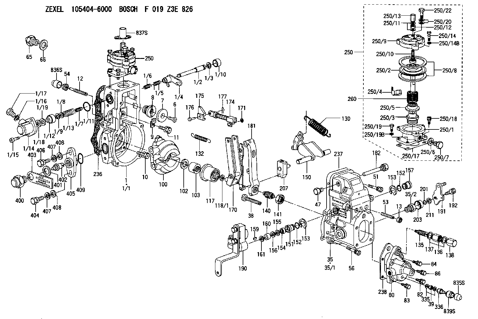
| 1. | [1] | 154620-0720 | GOVERNOR HOUSING |
| 1/1. | [1] | 154620-0020 | GOVERNOR HOUSING |
| 1/2. | [1] | 154621-3701 | LEVER SHAFT |
| 1/3. | [1] | 016010-0740 | LOCKING WASHER |
| 1/4. | [1] | 154415-3320 | CONTROL LEVER |
| 1/5. | [1] | 154415-3400 | COILED SPRING |
| 1/6. | [1] | 154621-3800 | COILED SPRING |
| 1/7. | [1] | 154621-4400 | COILED SPRING |
| 1/8. | [1] | 139406-1400 | SHIM |
| 1/9. | [1] | 016010-0540 | LOCKING WASHER |
| 1/10. | [1] | 154621-3600 | CAP |
| 1/11. | [1] | 016520-2210 | O-RING |
| 1/12. | [1] | 154621-3500 | BUSHING |
| 1/13. | [1] | 154621-3900 | COILED SPRING |
| 1/14. | [1] | 154620-1600 | COVER |
| 1/15. | [2] | 010235-1640 | HEX-SOCKET-HEAD CAP SCREW |
| 1/16. | [1] | 026510-1440 | GASKET D13.9&10.2T1 |
| 1/17. | [1] | 029111-0010 | CAPSULE |
| 1/18. | [1] | 139308-1500 | PLAIN WASHER D18&8T1.0 |
| 1/19. | [4] | 029300-7020 | PLAIN WASHER |
| 6. | [1] | 154621-4300 | BLEEDER SCREW |
| 7. | [1] | 154621-4100 | PLAIN WASHER |
| 8. | [1] | 154620-7900 | ADAPTOR |
| 9. | [1] | 154375-9020 | PLATE |
| 10. | [5] | 029010-6810 | BLEEDER SCREW |
| 11. | [1] | 020106-1840 | BLEEDER SCREW M6P1L18 |
| 12. | [1] | 154013-6000 | FLAT-HEAD SCREW |
| 13. | [1] | 154011-0100 | HEXAGON NUT |
| 35. | [1] | 154501-1720 | GOVERNOR COVER |
| 35/1. | [1] | 154501-1700 | GOVERNOR COVER |
| 35/2. | [1] | 154321-0400 | BUSHING |
| 38. | [1] | 154031-4700 | FLAT-HEAD SCREW |
| 39. | [1] | 139208-0400 | UNION NUT |
| 47. | [1] | 154036-0300 | CAPSULE |
| 51. | [2] | 139006-7100 | BLEEDER SCREW |
| 53. | [1] | 154010-0200 | FLAT-HEAD SCREW |
| 54. | [1] | 154011-4900 | UNION NUT |
| 56. | [4] | 020106-3840 | BLEEDER SCREW |
| 65. | [1] | 153020-5220 | STOPPING DEVICE |
| 66. | [1] | 026518-2240 | GASKET D21.9&18.2T1 |
| 80. | [1] | 154064-4200 | COVER |
| 82. | [1] | 020006-1640 | BLEEDER SCREW M6P1L16 4T |
| 83. | [1] | 020006-1640 | BLEEDER SCREW M6P1L16 4T |
| 84. | [1] | 020006-1640 | BLEEDER SCREW M6P1L16 4T |
| 86. | [1] | 020006-1640 | BLEEDER SCREW M6P1L16 4T |
| 100. | [1] | 154621-2520 | FLYWEIGHT ASSEMBLY |
| 102. | [1] | 029321-2020 | LOCKING WASHER |
| 103. | [1] | 029231-2030 | UNION NUT |
| 117. | [1] | 154123-2320 | SLIDING PIECE |
| 118/1. | [0] | 029311-0010 | SHIM D14&10.1T0.2 |
| 118/1. | [0] | 029311-0180 | SHIM D14&10.1T0.3 |
| 118/1. | [0] | 029311-0190 | SHIM D14&10.1T0.40 |
| 118/1. | [0] | 029311-0210 | SHIM D14&10.1T1 |
| 118/1. | [0] | 139410-0000 | SHIM D14.0&10.1T0.5 |
| 118/1. | [0] | 139410-0100 | SHIM D14.0&10.1T1.5 |
| 118/1. | [0] | 139410-3000 | SHIM D14&10.1T2.0 |
| 118/1. | [0] | 139410-3100 | SHIM D14&10.1T3.0 |
| 118/1. | [0] | 139410-3200 | SHIM D14&10.1T4.0 |
| 130. | [1] | 154150-0200 | GOVERNOR SPRING |
| 132. | [1] | 154154-5200 | COILED SPRING |
| 135. | [1] | 154158-5820 | HEADLESS SCREW |
| 136. | [1] | 029201-2290 | UNION NUT |
| 137. | [2] | 026512-1540 | GASKET D15.4&12.2T1.50 |
| 138. | [1] | 154159-1200 | CAP NUT |
| 140. | [1] | 154177-2420 | HEADLESS SCREW |
| 141. | [1] | 029201-6010 | UNION NUT |
| 150. | [1] | 154200-7020 | SWIVELLING LEVER |
| 151. | [1] | 154204-4300 | BUSHING |
| 152. | [2] | 029631-8020 | O-RING |
| 152. | [2] | 029631-8020 | O-RING |
| 153. | [2] | 016010-1640 | LOCKING WASHER |
| 153. | [2] | 016010-1640 | LOCKING WASHER |
| 154. | [1] | 139611-0000 | PACKING RING |
| 155. | [1] | 139411-0000 | SHIM |
| 156. | [0] | 029311-1070 | SHIM D16&11T0.5 |
| 157. | [1] | 154204-4400 | BUSHING |
| 159. | [1] | 025803-1310 | WOODRUFF KEY |
| 160. | [1] | 154206-2800 | BUSHING |
| 161. | [0] | 154206-0200 | PLAIN WASHER D19.5&11.2T1.0 |
| 170. | [1] | 154218-7320 | FORK LEVER |
| 171. | [1] | 016010-0540 | LOCKING WASHER |
| 174. | [1] | 154235-4720 | STRAP |
| 175. | [1] | 154232-3200 | CONNECTOR |
| 176. | [1] | 154222-5800 | BEARING PIN |
| 177. | [1] | 155402-3800 | SAFETY PIN |
| 181. | [1] | 154239-5120 | TENSIONING LEVER |
| 182. | [1] | 154237-1100 | BEARING PIN |
| 190. | [1] | 154396-8020 | CONTROL LEVER |
| 191. | [1] | 154382-3720 | CONTROL LEVER |
| 192. | [1] | 020006-1840 | BLEEDER SCREW M6P1L18 |
| 201. | [1] | 029631-0030 | O-RING &9.8W2.3 |
| 203. | [1] | 154322-0600 | CAP |
| 207. | [1] | 154326-5120 | CONTROL LEVER |
| 211. | [0] | 029311-0220 | SHIM D18&10.3T0.2 |
| 211B. | [0] | 029311-0230 | SHIM D18&10.3T0.5 |
| 236. | [1] | 154390-0000 | GASKET |
| 237. | [1] | 154390-0300 | GASKET |
| 238. | [1] | 154390-5000 | GASKET |
| 250. | [1] | 154422-7820 | MANIFOLD-PRESSURE COMP. |
| 250. | [1] | 154422-7820 | MANIFOLD-PRESSURE COMP. |
| 250/1. | [1] | 154422-7101 | DIAPHRAGM HOUSING |
| 250/2. | [1] | 154400-9520 | DIAPHRAGM |
| 250/3. | [1] | 154415-1200 | BUSHING |
| 250/4. | [1] | 146711-0000 | PLATE |
| 250/5. | [1] | 154415-1300 | UNION NUT |
| 250/6. | [1] | 029331-2130 | GASKET |
| 250/7. | [1] | 029111-2090 | CAPSULE |
| 250/8. | [2] | 154413-2600 | GASKET |
| 250/9. | [1] | 154404-5600 | COVER |
| 250/10. | [1] | 154415-1800 | FLAT-HEAD SCREW |
| 250/11. | [2] | 026506-1040 | GASKET D9.9&6.2T1 |
| 250/12. | [1] | 013030-6040 | UNION NUT M6P1H3.6 |
| 250/13. | [1] | 154035-1600 | CAP NUT |
| 250/14. | [3] | 154062-2900 | BLEEDER SCREW |
| 250/14B. | [3] | 014110-6440 | LOCKING WASHER |
| 250/17. | [1] | 154620-3200 | GASKET |
| 250/18. | [3] | 020106-1640 | BLEEDER SCREW M6P1.0L14 |
| 250/19. | [1] | 154062-5001 | BLEEDER SCREW |
| 250/19B. | [1] | 014110-6440 | LOCKING WASHER |
| 250/20. | [2] | 029341-0110 | GASKET |
| 250/22. | [1] | 029731-0120 | EYE BOLT |
| 260. | [1] | 154402-3000 | COILED SPRING |
| 335. | [2] | 026508-1140 | GASKET D11.4&8.2T1 |
| 336. | [1] | 154035-2900 | CAP NUT |
| 400. | [1] | 154621-3000 | CAPSULE |
| 401. | [1] | 026518-2240 | GASKET D21.9&18.2T1 |
| 402. | [1] | 154620-8800 | BEARING PIN |
| 403. | [1] | 154620-8901 | PLATE |
| 404. | [1] | 010038-1840 | BLEEDER SCREW M8P1.25L18 |
| 405. | [1] | 154620-1500 | FLANGE BUSHING |
| 406. | [1] | 154620-4700 | BLEEDER SCREW |
| 407. | [2] | 014110-8440 | LOCKING WASHER |
| 407. | [2] | 014110-8440 | LOCKING WASHER |
| 408. | [2] | 014010-8140 | PLAIN WASHER D18&8.5T1.6 |
| 408. | [2] | 014010-8140 | PLAIN WASHER D18&8.5T1.6 |
| 409. | [1] | 154621-3200 | O-RING |
| 835S. | [1] | 154062-4020 | CAP |
| 836S. | [1] | 154062-3520 | CAP |
| 837S. | [1] | 154062-2720 | CAP |
| 839S. | [1] | 154062-3900 | ADAPTOR |
Include in #1:
101609-3710
as GOVERNOR
Cross reference number
Zexel num
Bosch num
Firm num
Name
105404-6000
GOVERNOR
14JB GOV RSV GOV
14JB GOV RSV GOV
Information:
Care must be taken to ensure that fluids are contained during performance of inspection, maintenance, testing, adjusting and repair of the product. Be prepared to collect the fluid with suitable containers before opening any compartment or disassembling any component containing fluids.Refer to Special Publication, NENG2500, "Caterpillar Tools and Shop Products Guide" for tools and supplies suitable to collect and contain fluids on Caterpillar products.Dispose of all fluids according to local regulations and mandates.
Remove any coolant lines that may interfere with the installation. Remove any air inlet lines that may interfere with the installation.
Illustration 1 g01006397
Typical example (1) Bolt (2) Washer (3) Air inlet cover
Remove bolt (1) and the washer (2) from the air inlet cover (3). Discard the bolt (1) and the washer (2) .
Disconnect the electrical connector of the injection actuation pressure control valve (7). Remove the injection actuation pressure control valve (7) from the pump. Retain the injection actuation pressure control valve (7) for the reinstallation.Note: Modifications to the tools may need to be made in order to reduce interference with engine components.
Illustration 2 g01007381
Modified 2P-5494 crowfoot wrench
Remove the hose assembly (5), the connector (8), and the elbow (6). Discard these parts.
Illustration 3 g01006381
(4) HEUI pump (5) Flexible oil line (6) Elbow (7) Injection actuation pressure control valve (8) ConnectorInstallation of the 240-0716 Tube Kit
Illustration 4 g01006407
(4) HEUI pump (7) Injection actuation pressure control valve (9) Connector (10) Clip (11) Washer (12) Bolt (13) Spacer (14) Tube assembly (15) O-ring (16) O-ring (17) Elbow
Illustration 5 g01006437
(7) Injection actuation pressure control valve (9) Connector (15) O-ring (16) O-ring (17) Elbow
Apply a light coat of oil to the O-rings (15) and (16) during installation. Install the O-ring (15) on the connector (9). Install the O-ring (16) on the connector (9). Thread the connector (9) into the port on the cylinder head by hand. Tighten to 48 + 5 N m (35 + 4 lb ft).
Apply a light coat of oil to the O-rings (15) and (16) during installation. Install the O-ring (15) on the elbow (17). Install the O-ring (16) on the elbow (17).
Back off the jam nut on the elbow (17) to the top of the threads on the elbow assembly (17). Push the washer tightly against the jam nut. Check that the washer is as tight as possible. Thread the elbow assembly (17) into the port of the HEUI pump (4). Hand tighten the elbow (17) into the port of the HEUI pump until the washer is tight against the HEUI pump (4). Unscrew the elbow assembly (17) no more than one complete turn to 40 degrees.
Align the tube assembly (14) with the connector (9) and the elbow (17). Loosely thread each end of the tube assembly (14) onto the connector (9) and the elbow (17). Position the elbow (17) in order to not create stress in the tube assembly (14) .
Attach the clip (10) to the tube assembly (14). The flat side of the clip (10) must be toward the air inlet cover. Place the washer (11) onto the bolt
Have questions with 105404-6000?
Group cross 105404-6000 ZEXEL
105404-6000
GOVERNOR