Information governor
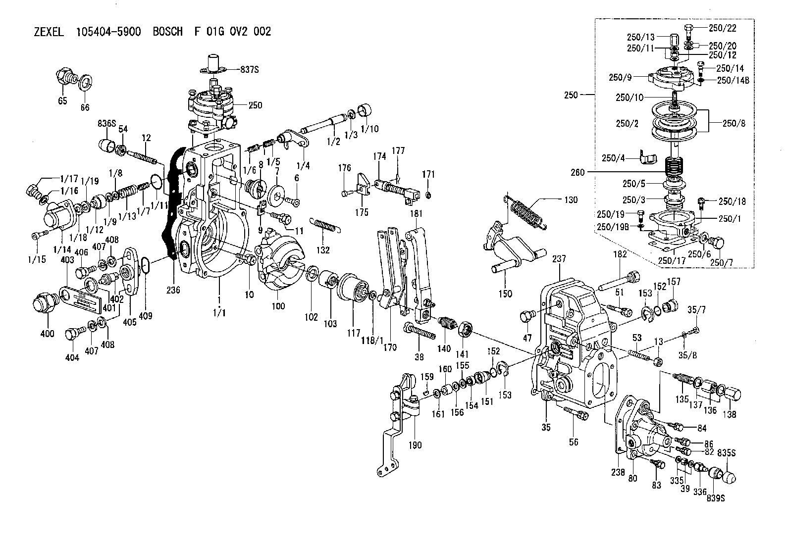
BOSCH
F 01G 0V2 002
f01g0v2002
ZEXEL
105404-5900
1054045900

Rating:
Scheme ###:
| 1. | [1] | 154620-0720 | GOVERNOR HOUSING |
| 1/1. | [1] | 154620-0020 | GOVERNOR HOUSING |
| 1/2. | [1] | 154621-3701 | LEVER SHAFT |
| 1/3. | [1] | 016010-0740 | LOCKING WASHER |
| 1/4. | [1] | 154415-3320 | CONTROL LEVER |
| 1/5. | [1] | 154415-3400 | COILED SPRING |
| 1/6. | [1] | 154621-3800 | COILED SPRING |
| 1/7. | [1] | 154621-4400 | COILED SPRING |
| 1/8. | [1] | 139406-1400 | SHIM |
| 1/9. | [1] | 016010-0540 | LOCKING WASHER |
| 1/10. | [1] | 154621-3600 | CAP |
| 1/11. | [1] | 016520-2210 | O-RING |
| 1/12. | [1] | 154621-3500 | BUSHING |
| 1/13. | [1] | 154621-3900 | COILED SPRING |
| 1/14. | [1] | 154620-1600 | COVER |
| 1/15. | [2] | 010235-1640 | HEX-SOCKET-HEAD CAP SCREW |
| 1/16. | [1] | 026510-1440 | GASKET D13.9&10.2T1 |
| 1/17. | [1] | 029111-0010 | CAPSULE |
| 1/18. | [1] | 139308-1500 | PLAIN WASHER D18&8T1.0 |
| 1/19. | [4] | 029300-7020 | PLAIN WASHER |
| 6. | [1] | 154621-4300 | BLEEDER SCREW |
| 7. | [1] | 154621-4100 | PLAIN WASHER |
| 8. | [1] | 154620-7900 | ADAPTOR |
| 9. | [1] | 154375-9020 | PLATE |
| 10. | [5] | 029010-6810 | BLEEDER SCREW |
| 11. | [1] | 020106-1840 | BLEEDER SCREW M6P1L18 |
| 12. | [1] | 154013-4000 | FLAT-HEAD SCREW |
| 13. | [1] | 154011-0100 | HEXAGON NUT |
| 35. | [1] | 154022-8720 | GOVERNOR COVER |
| 35/7. | [1] | 154222-2700 | FLAT-HEAD SCREW |
| 35/8. | [1] | 014110-3440 | LOCKING WASHER |
| 38. | [1] | 154031-4700 | FLAT-HEAD SCREW |
| 39. | [1] | 139208-0400 | UNION NUT |
| 47. | [1] | 154036-0300 | CAPSULE |
| 51. | [2] | 139006-7100 | BLEEDER SCREW |
| 53. | [1] | 154010-0200 | FLAT-HEAD SCREW |
| 54. | [1] | 154011-4900 | UNION NUT |
| 56. | [4] | 020106-3840 | BLEEDER SCREW |
| 65. | [1] | 155404-5120 | STOPPING DEVICE |
| 66. | [1] | 026518-2240 | GASKET D21.9&18.2T1 |
| 80. | [1] | 154064-4200 | COVER |
| 82. | [1] | 020006-1640 | BLEEDER SCREW M6P1L16 4T |
| 83. | [1] | 020006-1640 | BLEEDER SCREW M6P1L16 4T |
| 84. | [1] | 020006-1640 | BLEEDER SCREW M6P1L16 4T |
| 86. | [1] | 020006-1640 | BLEEDER SCREW M6P1L16 4T |
| 100. | [1] | 154621-2520 | FLYWEIGHT ASSEMBLY |
| 102. | [1] | 029321-2020 | LOCKING WASHER |
| 103. | [1] | 029231-2030 | UNION NUT |
| 117. | [1] | 154123-2320 | SLIDING PIECE |
| 118/1. | [0] | 029311-0010 | SHIM D14&10.1T0.2 |
| 118/1. | [0] | 029311-0180 | SHIM D14&10.1T0.3 |
| 118/1. | [0] | 029311-0190 | SHIM D14&10.1T0.40 |
| 118/1. | [0] | 029311-0210 | SHIM D14&10.1T1 |
| 118/1. | [0] | 139410-0000 | SHIM D14.0&10.1T0.5 |
| 118/1. | [0] | 139410-0100 | SHIM D14.0&10.1T1.5 |
| 118/1. | [0] | 139410-3000 | SHIM D14&10.1T2.0 |
| 118/1. | [0] | 139410-3100 | SHIM D14&10.1T3.0 |
| 118/1. | [0] | 139410-3200 | SHIM D14&10.1T4.0 |
| 130. | [1] | 154150-0200 | GOVERNOR SPRING |
| 132. | [1] | 154154-5200 | COILED SPRING |
| 135. | [1] | 154158-5820 | HEADLESS SCREW |
| 136. | [1] | 029201-2290 | UNION NUT |
| 137. | [2] | 026512-1540 | GASKET D15.4&12.2T1.50 |
| 138. | [1] | 154159-1200 | CAP NUT |
| 140. | [1] | 154177-0520 | HEADLESS SCREW |
| 141. | [1] | 029201-6010 | UNION NUT |
| 150. | [1] | 154200-7020 | SWIVELLING LEVER |
| 151. | [1] | 154204-4300 | BUSHING |
| 152. | [2] | 029631-8020 | O-RING |
| 152. | [2] | 029631-8020 | O-RING |
| 153. | [2] | 016010-1640 | LOCKING WASHER |
| 153. | [2] | 016010-1640 | LOCKING WASHER |
| 154. | [1] | 139611-0000 | PACKING RING |
| 155. | [1] | 139411-0000 | SHIM |
| 156. | [0] | 029311-1070 | SHIM D16&11T0.5 |
| 157. | [1] | 154204-4400 | BUSHING |
| 159. | [1] | 025803-1310 | WOODRUFF KEY |
| 160. | [1] | 154206-2800 | BUSHING |
| 161. | [0] | 154206-0200 | PLAIN WASHER D19.5&11.2T1.0 |
| 170. | [1] | 154218-7320 | FORK LEVER |
| 171. | [1] | 016010-0540 | LOCKING WASHER |
| 174. | [1] | 154235-4720 | STRAP |
| 175. | [1] | 154232-3200 | CONNECTOR |
| 176. | [1] | 154222-5800 | BEARING PIN |
| 177. | [1] | 155402-3800 | SAFETY PIN |
| 181. | [1] | 154239-5120 | TENSIONING LEVER |
| 182. | [1] | 154237-1100 | BEARING PIN |
| 190. | [1] | 154395-8620 | CONTROL LEVER |
| 236. | [1] | 154390-0000 | GASKET |
| 237. | [1] | 154390-0300 | GASKET |
| 238. | [1] | 154390-5000 | GASKET |
| 250. | [1] | 154422-7820 | MANIFOLD-PRESSURE COMP. |
| 250. | [1] | 154422-7820 | MANIFOLD-PRESSURE COMP. |
| 250/1. | [1] | 154422-7101 | DIAPHRAGM HOUSING |
| 250/2. | [1] | 154400-9520 | DIAPHRAGM |
| 250/3. | [1] | 154415-1200 | BUSHING |
| 250/4. | [1] | 146711-0000 | PLATE |
| 250/5. | [1] | 154415-1300 | UNION NUT |
| 250/6. | [1] | 029331-2130 | GASKET |
| 250/7. | [1] | 029111-2090 | CAPSULE |
| 250/8. | [2] | 154413-2600 | GASKET |
| 250/9. | [1] | 154404-5600 | COVER |
| 250/10. | [1] | 154415-1800 | FLAT-HEAD SCREW |
| 250/11. | [2] | 026506-1040 | GASKET D9.9&6.2T1 |
| 250/12. | [1] | 013030-6040 | UNION NUT M6P1H3.6 |
| 250/13. | [1] | 154035-1600 | CAP NUT |
| 250/14. | [3] | 154062-2900 | BLEEDER SCREW |
| 250/14B. | [3] | 014110-6440 | LOCKING WASHER |
| 250/17. | [1] | 154620-3200 | GASKET |
| 250/18. | [3] | 020106-1640 | BLEEDER SCREW M6P1.0L14 |
| 250/19. | [1] | 154062-5001 | BLEEDER SCREW |
| 250/19B. | [1] | 014110-6440 | LOCKING WASHER |
| 250/20. | [2] | 029341-0110 | GASKET |
| 250/22. | [1] | 029731-0120 | EYE BOLT |
| 260. | [1] | 154402-3000 | COILED SPRING |
| 335. | [2] | 026508-1140 | GASKET D11.4&8.2T1 |
| 336. | [1] | 154035-2900 | CAP NUT |
| 400. | [1] | 154620-8700 | CAPSULE |
| 401. | [1] | 154620-3100 | GASKET D21.9&18.2T1 |
| 402. | [1] | 154620-8800 | BEARING PIN |
| 403. | [1] | 154620-8901 | PLATE |
| 404. | [1] | 010038-1840 | BLEEDER SCREW M8P1.25L18 |
| 405. | [1] | 154620-1500 | FLANGE BUSHING |
| 406. | [1] | 154620-4700 | BLEEDER SCREW |
| 407. | [2] | 014110-8440 | LOCKING WASHER |
| 407. | [2] | 014110-8440 | LOCKING WASHER |
| 408. | [2] | 014010-8140 | PLAIN WASHER D18&8.5T1.6 |
| 408. | [2] | 014010-8140 | PLAIN WASHER D18&8.5T1.6 |
| 409. | [1] | 154621-3200 | O-RING |
| 835S. | [1] | 154062-4020 | CAP |
| 836S. | [1] | 154062-3520 | CAP |
| 837S. | [1] | 154062-2720 | CAP |
| 839S. | [1] | 154062-3900 | ADAPTOR |
Include in #1:
101609-3660
as GOVERNOR
Cross reference number
Zexel num
Bosch num
Firm num
Name
Information:
Refer to Table 2 and find the engine current static timing ("deg BTC") with the corresponding timing dimension ("dim mm"). Because the current timing must be retarded by 2.5 degrees, subtract 2.5 from the current "deg BTC" and locate that value under the same heading. Refer to the corresponding "dim mm" for the correct timing dimension.An example is an engine that currently has a static timing of 20.0 degrees BTC and a 116.65 mm timing dimension. These values are listed under the heading of "High Speed High Overlap". The result of 20.0 minus 2.5 is 17.5. The 17.5 degrees BTC has a corresponding 117.62 mm timing dimension for the injector.Label the Engine for the New Timing Dimension
Illustration 8 g00977473
Typical engine Information PlateAfter the timing has been adjusted, alter the engine Information Plate. The Information Plate is glued between the two side covers at the rear of the engine on the right side of the cylinder block.You can carefully grind off the original timing dimension. Then etch the new timing dimension onto the plate. Otherwise, permanently remove the original timing dimension by grinding or by marking. Then, obtain a 236-1777 Instruction Plate (Fuel Injector Timing).
Illustration 9 g00988962
236-1777 Instruction Plate (Fuel Injector Timing) Stamp the new timing dimension and the part number of the fuel injector onto the instruction plate. The plate has an adhesive backing. Press the plate onto the engine below the engine original Information Plate.Additional Instructions and Assistance
For the procedure to set the fuel injector timing dimension, refer to the engine's Systems Operation/Testing and Adjusting, "Fuel Setting".