Information governor
BOSCH
F 01G 0V2 003
f01g0v2003
ZEXEL
105404-5830
1054045830
Rating:
Scheme ###:
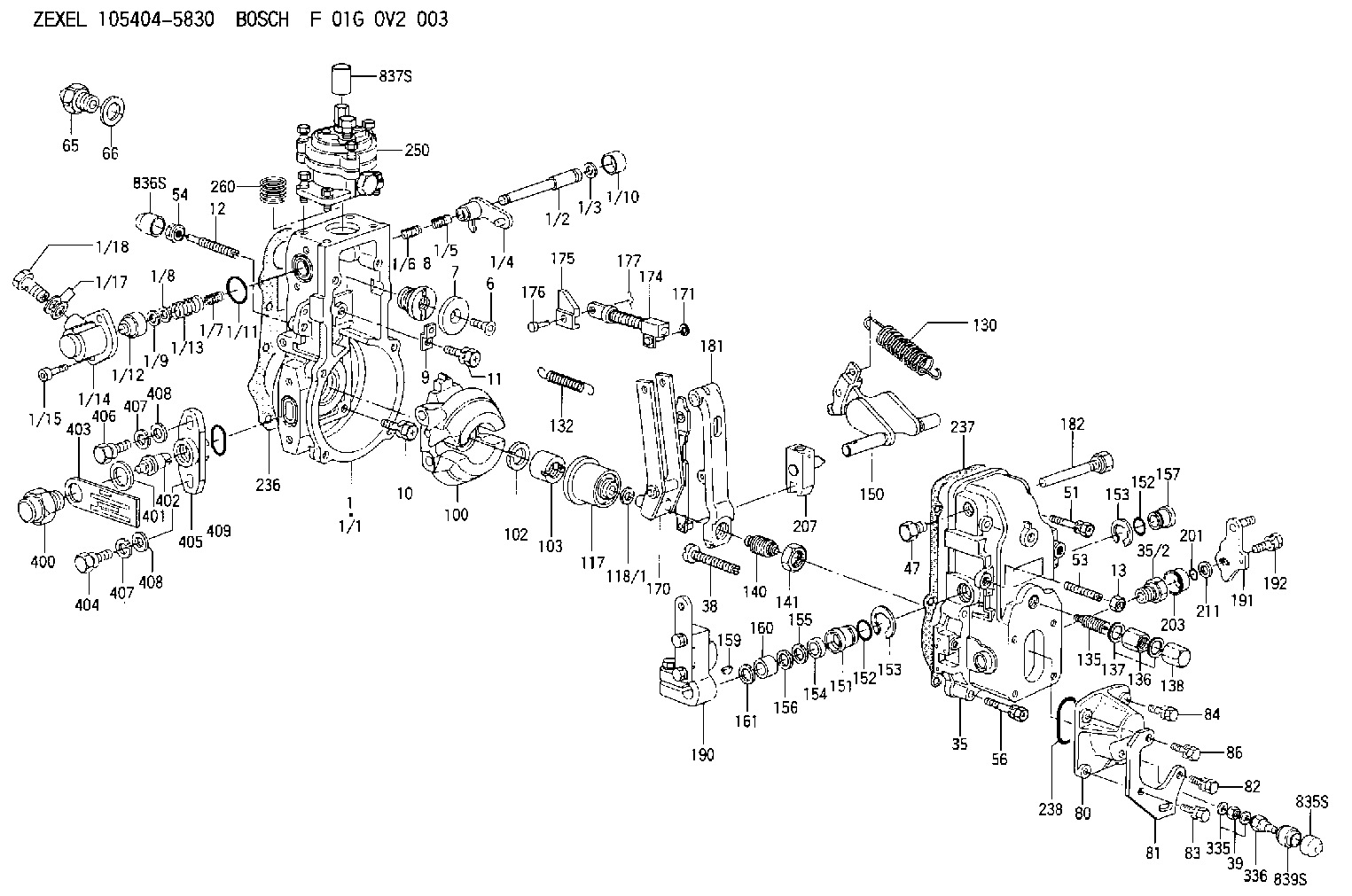
| 1. | [1] | 154620-0820 | GOVERNOR HOUSING |
| 1/1. | [1] | 154620-0020 | GOVERNOR HOUSING |
| 1/2. | [1] | 154621-3701 | LEVER SHAFT |
| 1/3. | [1] | 016010-0740 | LOCKING WASHER |
| 1/4. | [1] | 154415-3320 | CONTROL LEVER |
| 1/5. | [1] | 154415-3400 | COILED SPRING |
| 1/6. | [1] | 154621-3800 | COILED SPRING |
| 1/7. | [1] | 154621-4400 | COILED SPRING |
| 1/8. | [1] | 139406-1400 | SHIM |
| 1/9. | [1] | 016010-0540 | LOCKING WASHER |
| 1/10. | [1] | 154621-3600 | CAP |
| 1/11. | [1] | 016520-2210 | O-RING |
| 1/12. | [1] | 154621-3500 | BUSHING |
| 1/13. | [1] | 154621-3900 | COILED SPRING |
| 1/14. | [1] | 154620-1600 | COVER |
| 1/15. | [2] | 010235-1640 | HEX-SOCKET-HEAD CAP SCREW |
| 1/17. | [2] | 029341-0110 | GASKET |
| 1/18. | [1] | 029731-0120 | EYE BOLT |
| 6. | [1] | 154621-4300 | BLEEDER SCREW |
| 7. | [1] | 154621-4100 | PLAIN WASHER |
| 8. | [1] | 154620-7900 | ADAPTOR |
| 9. | [1] | 154375-9020 | PLATE |
| 10. | [5] | 029010-6810 | BLEEDER SCREW |
| 11. | [1] | 020106-1840 | BLEEDER SCREW M6P1L18 |
| 12. | [1] | 154013-6100 | FLAT-HEAD SCREW |
| 13. | [1] | 154011-0100 | HEXAGON NUT |
| 35. | [1] | 154500-3020 | GOVERNOR COVER |
| 35/2. | [1] | 154321-0400 | BUSHING |
| 38. | [1] | 154031-3000 | FLAT-HEAD SCREW |
| 39. | [1] | 139206-0600 | UNION NUT |
| 47. | [1] | 154036-0300 | CAPSULE |
| 51. | [2] | 139006-7100 | BLEEDER SCREW |
| 53. | [1] | 154010-0200 | FLAT-HEAD SCREW |
| 54. | [1] | 154011-4900 | UNION NUT |
| 56. | [4] | 020106-3840 | BLEEDER SCREW |
| 65. | [1] | 155404-3500 | CAP |
| 66. | [1] | 026518-2240 | GASKET D21.9&18.2T1 |
| 80. | [1] | 154063-5100 | COVER |
| 81. | [1] | 154358-7200 | BRACKET |
| 82. | [1] | 029020-6260 | BLEEDER SCREW |
| 83. | [1] | 029020-6260 | BLEEDER SCREW |
| 84. | [1] | 020006-1640 | BLEEDER SCREW M6P1L16 4T |
| 86. | [1] | 020006-2040 | BLEEDER SCREW M6P1L20 4T |
| 100. | [1] | 154621-2120 | FLYWEIGHT ASSEMBLY |
| 102. | [1] | 029321-2020 | LOCKING WASHER |
| 103. | [1] | 029231-2030 | UNION NUT |
| 117. | [1] | 154123-0120 | SLIDING PIECE |
| 118/1. | [0] | 029311-0010 | SHIM D14&10.1T0.2 |
| 118/1. | [0] | 029311-0180 | SHIM D14&10.1T0.3 |
| 118/1. | [0] | 029311-0190 | SHIM D14&10.1T0.40 |
| 118/1. | [0] | 029311-0210 | SHIM D14&10.1T1 |
| 118/1. | [0] | 139410-0000 | SHIM D14.0&10.1T0.5 |
| 118/1. | [0] | 139410-0100 | SHIM D14.0&10.1T1.5 |
| 118/1. | [0] | 139410-3000 | SHIM D14&10.1T2.0 |
| 118/1. | [0] | 139410-3100 | SHIM D14&10.1T3.0 |
| 118/1. | [0] | 139410-3200 | SHIM D14&10.1T4.0 |
| 130. | [1] | 154150-0400 | GOVERNOR SPRING |
| 132. | [1] | 154154-5200 | COILED SPRING |
| 135. | [1] | 154158-0920 | HEADLESS SCREW |
| 136. | [1] | 154011-1700 | UNION NUT |
| 137. | [2] | 026512-1540 | GASKET D15.4&12.2T1.50 |
| 138. | [1] | 154159-1200 | CAP NUT |
| 140. | [1] | 154177-0620 | HEADLESS SCREW |
| 141. | [1] | 029201-6010 | UNION NUT |
| 150. | [1] | 154200-7020 | SWIVELLING LEVER |
| 151. | [1] | 154204-4300 | BUSHING |
| 152. | [2] | 029631-8020 | O-RING |
| 152. | [2] | 029631-8020 | O-RING |
| 153. | [2] | 016010-1640 | LOCKING WASHER |
| 153. | [2] | 016010-1640 | LOCKING WASHER |
| 154. | [1] | 139611-0000 | PACKING RING |
| 155. | [1] | 139411-0000 | SHIM |
| 156. | [0] | 029311-1070 | SHIM D16&11T0.5 |
| 157. | [1] | 154204-4400 | BUSHING |
| 159. | [1] | 025803-1310 | WOODRUFF KEY |
| 160. | [1] | 154206-2800 | BUSHING |
| 161. | [0] | 154206-0200 | PLAIN WASHER D19.5&11.2T1.0 |
| 170. | [1] | 154218-1620 | FORK LEVER |
| 171. | [1] | 016010-0540 | LOCKING WASHER |
| 174. | [1] | 154234-4120 | STRAP |
| 175. | [1] | 154232-3200 | CONNECTOR |
| 176. | [1] | 154222-5800 | BEARING PIN |
| 177. | [1] | 155402-3800 | SAFETY PIN |
| 181. | [1] | 154236-4100 | TENSIONING LEVER |
| 182. | [1] | 154237-1100 | BEARING PIN |
| 190. | [1] | 154342-2320 | CONTROL LEVER |
| 191. | [1] | 154382-3720 | CONTROL LEVER |
| 192. | [1] | 020006-1840 | BLEEDER SCREW M6P1L18 |
| 201. | [1] | 029631-0030 | O-RING &9.8W2.3 |
| 203. | [1] | 154322-0600 | CAP |
| 207. | [1] | 154326-5120 | CONTROL LEVER |
| 211. | [0] | 029311-0220 | SHIM D18&10.3T0.2 |
| 211B. | [0] | 029311-0230 | SHIM D18&10.3T0.5 |
| 236. | [1] | 154390-0000 | GASKET |
| 237. | [1] | 154390-0300 | GASKET |
| 238. | [1] | 029635-2020 | O-RING |
| 250. | [1] | 154422-7820 | MANIFOLD-PRESSURE COMP. |
| 260. | [1] | 154403-8500 | COILED SPRING |
| 335. | [2] | 026506-1040 | GASKET D9.9&6.2T1 |
| 336. | [1] | 154035-2800 | CAP NUT |
| 400. | [1] | 154621-3000 | CAPSULE |
| 401. | [1] | 026518-2240 | GASKET D21.9&18.2T1 |
| 402. | [1] | 154620-8800 | BEARING PIN |
| 403. | [1] | 154620-8901 | PLATE |
| 404. | [1] | 010038-1840 | BLEEDER SCREW M8P1.25L18 |
| 405. | [1] | 154620-1500 | FLANGE BUSHING |
| 406. | [1] | 154620-4700 | BLEEDER SCREW |
| 407. | [2] | 014110-8440 | LOCKING WASHER |
| 407. | [2] | 014110-8440 | LOCKING WASHER |
| 408. | [2] | 014010-8140 | PLAIN WASHER D18&8.5T1.6 |
| 408. | [2] | 014010-8140 | PLAIN WASHER D18&8.5T1.6 |
| 409. | [1] | 154621-3200 | O-RING |
| 835S. | [1] | 154062-4020 | CAP |
| 836S. | [1] | 154062-3520 | CAP |
| 837S. | [1] | 154062-2720 | CAP |
| 839S. | [1] | 154062-3800 | ADAPTOR |
Cross reference number
Zexel num
Bosch num
Firm num
Name
Information:
C3.8 DPF
Illustration 14 g06047943
When the pin gauge is inserted into the cell hole, insert the gauge by lightly tapping on the pin with your finger tip. If the pin is pushed in by force, the pin can pierce through the ash and there would not be an accurate measurement.
After the DPF filter is cleaned, measure the depth of ash (depth of remaining ash) in 21 locations with a pin gauge of 0.5 mm to 1.0 mm in diameter, which is slightly less than the cell width at the positions.The minimum remaining ash depth is 106 mm (4.2 inch).The maximum depth is 140 mm (5.5 inch).
Table 2
Measurement Locations 21 Places
A 57 mm (2.2 inch)
B 57 mm (2.2 inch)
C 10 mm (0.4 inch)
D 35 mm (1.4 inch)
E 138 mm (5.4 inch)
F 35 mm (1.4 inch)
G 226 mm (8.9 inch)
If the depth of ash is out of the permissible range, the DPF filter cannot be reused. Replace the DPF filter with a new one.C3.3B DPF
Illustration 15 g03617080
When the pin gauge is inserted into the cell hole, insert the gauge by lightly tapping on the pin with your finger tip. If the pin is pushed in by force, the pin can pierce through the ash and there would not be an accurate measurement.
After the DPF filter is cleaned, measure the depth of ash (depth of remaining ash) in 25 locations with a pin gauge of 0.6 mm to 0.8 mm in diameter.C3.8 & C3.3B Engines - The minimum remaining ash depth is 119 mm (4.7 inch).
If the depth of ash is out of the permissible range, the DPF filter cannot be reused. Replace the DPF filter with a new one.C2.4 DPF
Illustration 16 g06047315
After the DPF filter is cleaned, measure the depth of ash (depth of remaining ash) in 16 locations with a pin gauge of 0.6 mm to 0.8 mm in diameter.C2.4 Engines (Naturally Aspirated) - The minimum remaining ash depth is 102 mm (4.0 inch).C2.4 Engines (Turbo) - The minimum remaining ash depth is 119 mm (4.7 inch).
If the depth of ash is out of the permissible range, the DPF filter cannot be reused. Replace the DPF filter with a new one.Assembly of the DPF Canister
Refer to the Disassembly and Assembly Manual, Diesel Particulate Filter - Assemble for the procedure to disassemble the DPF.
Illustration 17 g06047871
(14) Gas flow
Assemble the DPF filter in the right direction by referring to the arrow (14) on the side showing the flow of exhaust gas.
When installing the temperature sensor and differential pressure pipe, apply 4C-5599 Anti-Seize Compound to the threads.Note: Itis recommended to replacethe two differential pressure hoses.
If the engine is installed in the machine, refer to the machines Engine Supplement, Diesel Particulate Filter - Remove and Install for the procedure to install the DPF.Soot Load
The soot load reset should only be performed after the DPF is cleaned or a new DPF is installed. If the Soot Load Reset is performed any other times, soot load could cause the DPF to crack