Information governor
BOSCH
F 019 Z2E 033
f019z2e033
ZEXEL
105404-5820
1054045820

Rating:
Scheme ###:
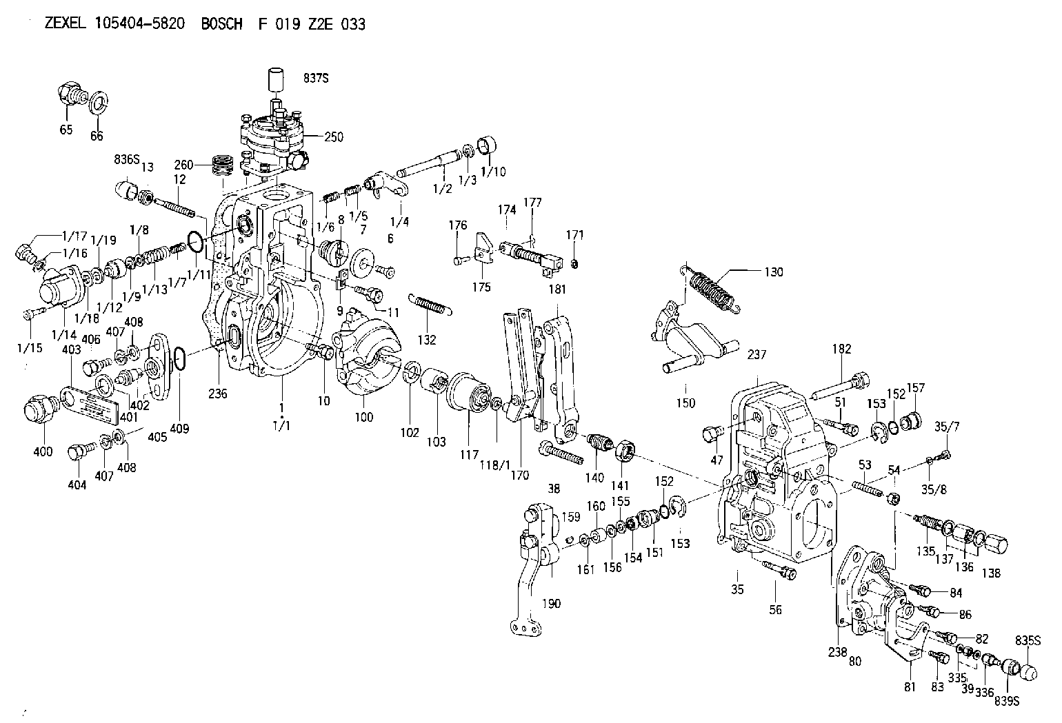
| 1. | [1] | 154620-0720 | GOVERNOR HOUSING |
| 1/1. | [1] | 154620-0020 | GOVERNOR HOUSING |
| 1/2. | [1] | 154621-3701 | LEVER SHAFT |
| 1/3. | [1] | 016010-0740 | LOCKING WASHER |
| 1/4. | [1] | 154415-3320 | CONTROL LEVER |
| 1/5. | [1] | 154415-3400 | COILED SPRING |
| 1/6. | [1] | 154621-3800 | COILED SPRING |
| 1/7. | [1] | 154621-4000 | COILED SPRING |
| 1/8. | [1] | 139406-1300 | SHIM |
| 1/9. | [1] | 016010-0540 | LOCKING WASHER |
| 1/10. | [1] | 154621-3600 | CAP |
| 1/11. | [1] | 016520-2210 | O-RING |
| 1/12. | [1] | 154621-3500 | BUSHING |
| 1/13. | [1] | 154621-3900 | COILED SPRING |
| 1/14. | [1] | 154620-1600 | COVER |
| 1/15. | [2] | 010235-1640 | HEX-SOCKET-HEAD CAP SCREW |
| 1/16. | [1] | 026510-1440 | GASKET D13.9&10.2T1 |
| 1/17. | [1] | 029111-0010 | CAPSULE |
| 1/18. | [1] | 139308-1500 | PLAIN WASHER D18&8T1.0 |
| 1/19. | [4] | 029300-7020 | PLAIN WASHER |
| 6. | [1] | 154621-4300 | BLEEDER SCREW |
| 7. | [1] | 154621-4100 | PLAIN WASHER |
| 8. | [1] | 154620-7900 | ADAPTOR |
| 9. | [1] | 154375-9020 | PLATE |
| 10. | [5] | 029010-6810 | BLEEDER SCREW |
| 11. | [1] | 020106-1840 | BLEEDER SCREW M6P1L18 |
| 12. | [1] | 154013-4000 | FLAT-HEAD SCREW |
| 12B. | [1] | 154013-5000 | FLAT-HEAD SCREW |
| 13. | [1] | 154011-0100 | HEXAGON NUT |
| 35. | [1] | 154022-8720 | GOVERNOR COVER |
| 35/7. | [1] | 154222-2700 | FLAT-HEAD SCREW |
| 35/8. | [1] | 014110-3440 | LOCKING WASHER |
| 38. | [1] | 154031-4700 | FLAT-HEAD SCREW |
| 39. | [1] | 139208-0400 | UNION NUT |
| 47. | [1] | 154036-0300 | CAPSULE |
| 51. | [2] | 139006-7100 | BLEEDER SCREW |
| 53. | [1] | 154010-0200 | FLAT-HEAD SCREW |
| 54. | [1] | 154011-4900 | UNION NUT |
| 56. | [4] | 020106-3840 | BLEEDER SCREW |
| 65. | [1] | 155404-5120 | STOPPING DEVICE |
| 66. | [1] | 026518-2240 | GASKET D21.9&18.2T1 |
| 80. | [1] | 154064-4200 | COVER |
| 81. | [1] | 154376-3000 | BRACKET |
| 82. | [1] | 029020-6260 | BLEEDER SCREW |
| 83. | [1] | 029020-6260 | BLEEDER SCREW |
| 84. | [1] | 020006-1640 | BLEEDER SCREW M6P1L16 4T |
| 86. | [1] | 020006-2040 | BLEEDER SCREW M6P1L20 4T |
| 100. | [1] | 154621-2520 | FLYWEIGHT ASSEMBLY |
| 102. | [1] | 029321-2020 | LOCKING WASHER |
| 103. | [1] | 029231-2030 | UNION NUT |
| 117. | [1] | 154123-2320 | SLIDING PIECE |
| 118/1. | [0] | 029311-0010 | SHIM D14&10.1T0.2 |
| 118/1. | [0] | 029311-0180 | SHIM D14&10.1T0.3 |
| 118/1. | [0] | 029311-0190 | SHIM D14&10.1T0.40 |
| 118/1. | [0] | 029311-0210 | SHIM D14&10.1T1 |
| 118/1. | [0] | 139410-0000 | SHIM D14.0&10.1T0.5 |
| 118/1. | [0] | 139410-0100 | SHIM D14.0&10.1T1.5 |
| 118/1. | [0] | 139410-3000 | SHIM D14&10.1T2.0 |
| 118/1. | [0] | 139410-3100 | SHIM D14&10.1T3.0 |
| 118/1. | [0] | 139410-3200 | SHIM D14&10.1T4.0 |
| 130. | [1] | 154151-1300 | GOVERNOR SPRING |
| 132. | [1] | 154154-5200 | COILED SPRING |
| 135. | [1] | 154158-5720 | HEADLESS SCREW |
| 136. | [1] | 029201-2290 | UNION NUT |
| 137. | [2] | 026512-1540 | GASKET D15.4&12.2T1.50 |
| 138. | [1] | 154159-1200 | CAP NUT |
| 140. | [1] | 154177-1820 | HEADLESS SCREW |
| 141. | [1] | 029201-6010 | UNION NUT |
| 150. | [1] | 154200-7020 | SWIVELLING LEVER |
| 151. | [1] | 154204-4300 | BUSHING |
| 152. | [2] | 029631-8020 | O-RING |
| 152. | [2] | 029631-8020 | O-RING |
| 153. | [2] | 016010-1640 | LOCKING WASHER |
| 153. | [2] | 016010-1640 | LOCKING WASHER |
| 154. | [1] | 139611-0000 | PACKING RING |
| 155. | [1] | 139411-0000 | SHIM |
| 156. | [0] | 029311-1070 | SHIM D16&11T0.5 |
| 157. | [1] | 154204-4400 | BUSHING |
| 159. | [1] | 025803-1310 | WOODRUFF KEY |
| 160. | [1] | 154206-2800 | BUSHING |
| 161. | [0] | 154206-0200 | PLAIN WASHER D19.5&11.2T1.0 |
| 170. | [1] | 154218-7320 | FORK LEVER |
| 171. | [1] | 016010-0540 | LOCKING WASHER |
| 174. | [1] | 154234-4120 | STRAP |
| 175. | [1] | 154232-3200 | CONNECTOR |
| 176. | [1] | 154222-5800 | BEARING PIN |
| 177. | [1] | 155402-3800 | SAFETY PIN |
| 181. | [1] | 154239-5120 | TENSIONING LEVER |
| 182. | [1] | 154237-1100 | BEARING PIN |
| 190. | [1] | 154395-8620 | CONTROL LEVER |
| 236. | [1] | 154390-0000 | GASKET |
| 237. | [1] | 154390-0300 | GASKET |
| 238. | [1] | 154390-5000 | GASKET |
| 250. | [1] | 154422-7820 | MANIFOLD-PRESSURE COMP. |
| 260. | [1] | 154402-3000 | COILED SPRING |
| 335. | [2] | 026508-1140 | GASKET D11.4&8.2T1 |
| 336. | [1] | 154035-2900 | CAP NUT |
| 400. | [1] | 154621-3000 | CAPSULE |
| 401. | [1] | 026518-2240 | GASKET D21.9&18.2T1 |
| 402. | [1] | 154620-8800 | BEARING PIN |
| 403. | [1] | 154620-8901 | PLATE |
| 404. | [1] | 010038-1840 | BLEEDER SCREW M8P1.25L18 |
| 405. | [1] | 154620-1500 | FLANGE BUSHING |
| 406. | [1] | 154620-4700 | BLEEDER SCREW |
| 407. | [2] | 014110-8440 | LOCKING WASHER |
| 407. | [2] | 014110-8440 | LOCKING WASHER |
| 408. | [2] | 014010-8140 | PLAIN WASHER D18&8.5T1.6 |
| 408. | [2] | 014010-8140 | PLAIN WASHER D18&8.5T1.6 |
| 409. | [1] | 154621-3200 | O-RING |
| 835S. | [1] | 154062-4020 | CAP |
| 836S. | [1] | 154062-3520 | CAP |
| 837S. | [1] | 154062-2720 | CAP |
| 839S. | [1] | 154062-3900 | ADAPTOR |
Include in #1:
101609-3600
as GOVERNOR
Cross reference number
Zexel num
Bosch num
Firm num
Name
Information:
Remove The Fan
Illustration 1 g00871386
(1) Cable (2) Fan (3) Guard (4) Screws (5) Filter (6) Cover
Disconnect the power to the monitor.
Remove cover (6) and remove filter (5) .
Remove guard (3) by removing screws (4) that hold guard (3) in place.
Remove the back cover of the monitor by removing the 8 screws that hold the back cover in place. Refer to Testing And Adjusting, "Cover - Remove" for details on removing the back cover.
Remove the two wire ties that secure the power wires around fan (2) .
Illustration 2 g00871408
CPU Board (7) Connector
Follow cable (1) and disconnect the connector from CPU board (7). Disconnect the connector by pulling on the connector. Do not pull on the wires.
Remove fan (2) from the monitor.Install The Fan
Connect the connector of cable (1) to the CPU board (7) .
Position fan (2) so that the power wires are routed above fan (2) .
Secure fan (2) and secure guard (3) with screws (4) .
Replace filter (5) and replace cover (6) .
Secure the power wires to fan (2) by using the wire ties.
Replace the back cover of the monitor by using the 8 screws.