Information governor
BOSCH
9 420 611 670
9420611670
ZEXEL
105404-5440
1054045440
Rating:
Scheme ###:
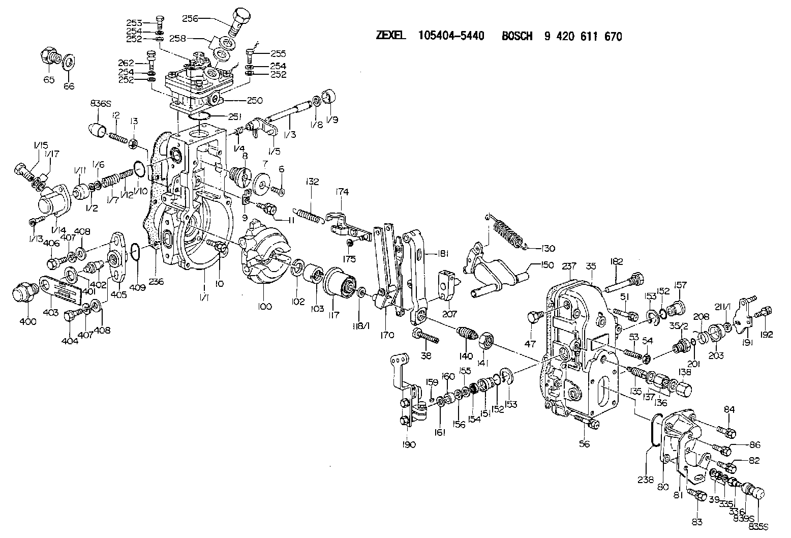
| 1. | [1] | 154620-0120 | GOVERNOR HOUSING |
| 1/1. | [1] | 154620-0020 | GOVERNOR HOUSING |
| 1/2. | [1] | 154620-5300 | PLAIN WASHER |
| 1/3. | [1] | 154620-6100 | LEVER SHAFT |
| 1/4. | [1] | 154621-0100 | COILED SPRING |
| 1/5. | [1] | 154620-2320 | CONTROL LEVER |
| 1/6. | [1] | 154620-5400 | SHIM |
| 1/7. | [1] | 154621-0200 | COILED SPRING |
| 1/8. | [1] | 154620-5500 | PLAIN WASHER |
| 1/9. | [1] | 154620-2400 | CAP |
| 1/10. | [1] | 154620-8200 | O-RING |
| 1/11. | [1] | 154620-7600 | BUSHING |
| 1/12. | [1] | 154621-0300 | COILED SPRING |
| 1/13. | [2] | 154620-4800 | BLEEDER SCREW |
| 1/14. | [1] | 154620-1200 | COVER |
| 1/15. | [1] | 029731-0120 | EYE BOLT |
| 1/17. | [2] | 029341-0110 | GASKET |
| 6. | [1] | 154621-4300 | BLEEDER SCREW |
| 7. | [1] | 154621-4100 | PLAIN WASHER |
| 8. | [1] | 154620-7900 | ADAPTOR |
| 9. | [1] | 154375-9020 | PLATE |
| 10. | [5] | 029010-6810 | BLEEDER SCREW |
| 11. | [1] | 020106-1840 | BLEEDER SCREW M6P1L18 |
| 12. | [1] | 154013-6100 | FLAT-HEAD SCREW |
| 13. | [1] | 154011-0100 | HEXAGON NUT |
| 35. | [1] | 154500-3020 | GOVERNOR COVER |
| 35/2. | [1] | 154321-0400 | BUSHING |
| 38. | [1] | 154031-3000 | FLAT-HEAD SCREW |
| 39. | [1] | 139206-0600 | UNION NUT |
| 47. | [1] | 154036-0300 | CAPSULE |
| 51. | [2] | 139006-7100 | BLEEDER SCREW |
| 53. | [1] | 154010-0200 | FLAT-HEAD SCREW |
| 54. | [1] | 154011-4900 | UNION NUT |
| 56. | [4] | 020106-3840 | BLEEDER SCREW |
| 65. | [1] | 155404-5120 | STOPPING DEVICE |
| 66. | [1] | 026518-2240 | GASKET D21.9&18.2T1 |
| 80. | [1] | 154063-5100 | COVER |
| 81. | [1] | 154358-7200 | BRACKET |
| 82. | [1] | 020006-2040 | BLEEDER SCREW M6P1L20 4T |
| 83. | [1] | 020006-2040 | BLEEDER SCREW M6P1L20 4T |
| 84. | [1] | 020006-1640 | BLEEDER SCREW M6P1L16 4T |
| 86. | [1] | 020006-2040 | BLEEDER SCREW M6P1L20 4T |
| 100. | [1] | 154621-2120 | FLYWEIGHT ASSEMBLY |
| 102. | [1] | 029321-2020 | LOCKING WASHER |
| 103. | [1] | 029231-2030 | UNION NUT |
| 117. | [1] | 154123-0120 | SLIDING PIECE |
| 118/1. | [0] | 029311-0010 | SHIM D14&10.1T0.2 |
| 118/1. | [0] | 029311-0180 | SHIM D14&10.1T0.3 |
| 118/1. | [0] | 029311-0190 | SHIM D14&10.1T0.40 |
| 118/1. | [0] | 029311-0210 | SHIM D14&10.1T1 |
| 118/1. | [0] | 139410-0000 | SHIM D14.0&10.1T0.5 |
| 118/1. | [0] | 139410-0100 | SHIM D14.0&10.1T1.5 |
| 118/1. | [0] | 139410-3000 | SHIM D14&10.1T2.0 |
| 118/1. | [0] | 139410-3100 | SHIM D14&10.1T3.0 |
| 118/1. | [0] | 139410-3200 | SHIM D14&10.1T4.0 |
| 130. | [1] | 154150-0400 | GOVERNOR SPRING |
| 132. | [1] | 154154-5200 | COILED SPRING |
| 135. | [1] | 154158-0920 | HEADLESS SCREW |
| 136. | [1] | 154011-1700 | UNION NUT |
| 137. | [2] | 026512-1540 | GASKET D15.4&12.2T1.50 |
| 138. | [1] | 154159-1200 | CAP NUT |
| 140. | [1] | 154177-1020 | HEADLESS SCREW |
| 141. | [1] | 029201-6010 | UNION NUT |
| 150. | [1] | 154200-7020 | SWIVELLING LEVER |
| 151. | [1] | 154204-3000 | BUSHING |
| 152. | [2] | 029631-8020 | O-RING |
| 152. | [2] | 029631-8020 | O-RING |
| 153. | [2] | 016010-1640 | LOCKING WASHER |
| 153. | [2] | 016010-1640 | LOCKING WASHER |
| 154. | [1] | 139611-0000 | PACKING RING |
| 155. | [1] | 139411-0000 | SHIM |
| 156. | [0] | 029311-1070 | SHIM D16&11T0.5 |
| 157. | [1] | 154204-3100 | BUSHING |
| 159. | [1] | 025803-1310 | WOODRUFF KEY |
| 160. | [1] | 154206-2800 | BUSHING |
| 161. | [0] | 154206-0200 | PLAIN WASHER D19.5&11.2T1.0 |
| 170. | [1] | 154211-4420 | FORK LEVER |
| 174. | [1] | 154620-2520 | STRAP |
| 175. | [1] | 016010-0540 | LOCKING WASHER |
| 181. | [1] | 154236-4100 | TENSIONING LEVER |
| 182. | [1] | 154237-1100 | BEARING PIN |
| 190. | [1] | 154343-9220 | CONTROL LEVER |
| 191. | [1] | 154382-3720 | CONTROL LEVER |
| 192. | [1] | 020006-1840 | BLEEDER SCREW M6P1L18 |
| 201. | [1] | 029631-0030 | O-RING &9.8W2.3 |
| 203. | [1] | 154322-0100 | CAP |
| 207. | [1] | 154326-8520 | LEVER GROUP |
| 208. | [1] | 154327-7300 | COILED SPRING |
| 211/1. | [0] | 029311-0520 | SHIM D20.8&10.3T0.2 |
| 211/1. | [0] | 029311-0530 | SHIM D20.8&10.3T0.25 |
| 211/1. | [0] | 029311-0540 | SHIM D20.8&10.3T0.3 |
| 211/1. | [0] | 029311-0550 | SHIM D20.8&10.3T0.35 |
| 211/1. | [0] | 029311-0560 | SHIM D20.8&10.3T0.4 |
| 211/1. | [0] | 029311-0570 | SHIM D20.8&10.3T0.5 |
| 236. | [1] | 154390-0000 | GASKET |
| 237. | [1] | 154390-0300 | GASKET |
| 238. | [1] | 029635-2020 | O-RING |
| 250. | [1] | 154422-2620 | MANIFOLD-PRESSURE COMP. |
| 251. | [1] | 016560-2610 | O-RING |
| 252. | [4] | 014020-6140 | PLAIN WASHER |
| 252. | [4] | 014020-6140 | PLAIN WASHER |
| 252. | [4] | 014020-6140 | PLAIN WASHER |
| 253. | [1] | 010006-1640 | BLEEDER SCREW M6P1L16 4T |
| 254. | [4] | 014110-6440 | LOCKING WASHER |
| 254. | [4] | 014110-6440 | LOCKING WASHER |
| 254. | [4] | 014110-6440 | LOCKING WASHER |
| 255. | [2] | 010006-1640 | BLEEDER SCREW M6P1L16 4T |
| 256. | [1] | 029731-2040 | EYE BOLT |
| 258. | [2] | 029341-2140 | GASKET |
| 262. | [1] | 154062-5001 | BLEEDER SCREW |
| 335. | [2] | 026506-1040 | GASKET D9.9&6.2T1 |
| 336. | [1] | 154035-2800 | CAP NUT |
| 400. | [1] | 154620-8700 | CAPSULE |
| 401. | [1] | 154620-3100 | GASKET |
| 402. | [1] | 154620-8800 | BEARING PIN |
| 403. | [1] | 154620-8900 | PLATE |
| 404. | [1] | 010038-1840 | BLEEDER SCREW M8P1.25L18 |
| 405. | [1] | 154620-1500 | FLANGE BUSHING |
| 406. | [1] | 154620-4700 | BLEEDER SCREW |
| 407. | [2] | 014110-8440 | LOCKING WASHER |
| 407. | [2] | 014110-8440 | LOCKING WASHER |
| 408. | [2] | 014010-8140 | PLAIN WASHER D18&8.5T1.6 |
| 408. | [2] | 014010-8140 | PLAIN WASHER D18&8.5T1.6 |
| 409. | [1] | 154620-9000 | O-RING |
Include in #1:
101405-3010
as GOVERNOR
Cross reference number
Zexel num
Bosch num
Firm num
Name
Information:
Use tool (E) in order to cut off the part of rivet (1) that has been peened. Remove rivet (1) from fuel injection control linkage (4) .
Illustration 13 g00702186
The 180-7951 Bushing Assembly Kit (F) Rack Control Shaft (G) Governor Link (4) Fuel Injection Control Linkage (7) 180-7952 Lever Bushing (8) 8L-5832 Hex Nut (9) 9X-8907 Hexagon Button Screw
Use the 180-7951 Bushing Assembly Kit in order to modify the linkage. Insert 9X-8907 Hexagon Button Screw (9) from the 180-7951 Bushing Assembly Kit into fuel injection control linkage (4). Refer to Illustration 13.
Apply 169-5464 Quick Cure Primer apply on the threads of 9X-8907 Hexagon Button Screw (9) and 8L-5832 Hex Nut (8). Allow the primer to dry. The Quick Cure Primer counteracts the effects of the Volatile Corrosion Inhibitor (VCI) paper that was used to package the parts.
Assemble 180-7952 Lever Bushing (7) on 9X-8907 Hexagon Button Screw (9). Refer to Illustration 13.
Apply the 154-9731 Thread Lock Compound on the threads of 9X-8907 Hexagon Button Screw (9) and 8L-5832 Hex Nut (8) .
Illustration 14 g00655322
Place 8L-5832 Hex Nut (8) on 9X-8907 Hexagon Button Screw (9). Tighten 8L-5832 Hex Nut (8) until hex nut (8) is snug. Tighten 8L-5832 Hex Nut (8) for an additional 180 degrees.
Do not let metal chips or pieces of the rivet fall into the engine.
Illustration 15 g00655325
Clean the fuel injection control linkage and clean the surfaces of the cylinder head that are adjacent to the fuel injection control linkage with shop solvent. Remove the towels and remove all debris very carefully.
Install the 180-7956 Clamp Assembly Kit . Refer to the "Installation Of The 180-7956 Clamp Assembly Kit " section of this publication.Installation Of The 180-7956 Clamp Assembly Kit
Note: The 180-7956 Clamp Assembly Kit is used for the former control linkages only.Note: If the 180-7956 Clamp Assembly Kit is installed, refer to ""Modification of the 128-9640 Injector Synchronization Fixture "".The 180-7956 Clamp Assembly Kit may be installed on the fuel injection control linkage. The 180-7956 Clamp Assembly Kit will increase the strength of the joint.
Illustration 16 g00655326
Install 183-9390 Spacer (10) on fuel injection control linkage (4). Refer to Illustration 16.
Apply 169-5464 Quick Cure Primer to the threaded hole in the 180-7954 Clamp (11). Apply 169-5464 Quick Cure Primer to the threads of screw (13). Allow the primer to dry. The Quick Cure Primer counteracts the effects of the Volatile Corrosion Inhibitor (VCI) paper that was used to package the parts.
Apply 154-9731 Thread Lock Compound to the threaded hole in the 180-7954 Clamp (11). Apply 154-9731 Thread Lock Compound to the threads of screw (13) of clamp assembly. Loosely assemble 180-7954 Clamp (11) and 180-7987 Clamp (12) on fuel injection control linkage (4). Refer to Illustration 16. Be sure that the rivet head or bushing (14) is fully engaged into the counterbore of the