Information governor
BOSCH
9 420 610 353
9420610353
ZEXEL
105404-5250
1054045250

Rating:
Scheme ###:
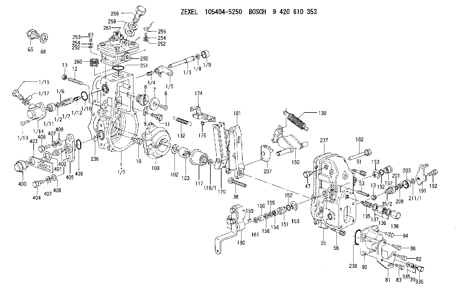
| 1. | [1] | 154620-0120 | GOVERNOR HOUSING |
| 1/1. | [1] | 154620-0020 | GOVERNOR HOUSING |
| 1/2. | [1] | 154620-5300 | PLAIN WASHER |
| 1/3. | [1] | 154620-6100 | LEVER SHAFT |
| 1/4. | [1] | 154621-0100 | COILED SPRING |
| 1/5. | [1] | 154620-2320 | CONTROL LEVER |
| 1/6. | [1] | 154620-5400 | SHIM |
| 1/7. | [1] | 154621-0200 | COILED SPRING |
| 1/8. | [1] | 154620-5500 | PLAIN WASHER |
| 1/9. | [1] | 154620-2400 | CAP |
| 1/10. | [1] | 154620-8200 | O-RING |
| 1/11. | [1] | 154620-7600 | BUSHING |
| 1/12. | [1] | 154621-0300 | COILED SPRING |
| 1/13. | [2] | 154620-4800 | BLEEDER SCREW |
| 1/14. | [1] | 154620-1200 | COVER |
| 1/15. | [1] | 029731-0120 | EYE BOLT |
| 1/17. | [2] | 029341-0110 | GASKET |
| 6. | [1] | 154621-4300 | BLEEDER SCREW |
| 7. | [1] | 154621-4100 | PLAIN WASHER |
| 8. | [1] | 154620-7900 | ADAPTOR |
| 9. | [1] | 154375-9020 | PLATE |
| 10. | [5] | 029010-6810 | BLEEDER SCREW |
| 11. | [1] | 020106-1840 | BLEEDER SCREW M6P1L18 |
| 12. | [1] | 154010-0100 | FLAT-HEAD SCREW |
| 13. | [2] | 154011-0100 | HEXAGON NUT |
| 13. | [2] | 154011-0100 | HEXAGON NUT |
| 35. | [1] | 154500-3020 | GOVERNOR COVER |
| 35/2. | [1] | 154321-0400 | BUSHING |
| 38. | [1] | 154031-3000 | FLAT-HEAD SCREW |
| 39. | [1] | 139206-0600 | UNION NUT |
| 47. | [1] | 154036-0300 | CAPSULE |
| 51. | [2] | 139006-7100 | BLEEDER SCREW |
| 53. | [1] | 154010-0200 | FLAT-HEAD SCREW |
| 56. | [4] | 020106-3840 | BLEEDER SCREW |
| 65. | [1] | 155404-5120 | STOPPING DEVICE |
| 66. | [1] | 026518-2240 | GASKET D21.9&18.2T1 |
| 80. | [1] | 154063-5100 | COVER |
| 81. | [1] | 154358-7200 | BRACKET |
| 82. | [1] | 029020-6260 | BLEEDER SCREW |
| 83. | [1] | 029020-6260 | BLEEDER SCREW |
| 84. | [1] | 020006-1640 | BLEEDER SCREW M6P1L16 4T |
| 86. | [1] | 020006-2040 | BLEEDER SCREW M6P1L20 4T |
| 100. | [1] | 154621-2120 | FLYWEIGHT ASSEMBLY |
| 102. | [1] | 029321-2020 | LOCKING WASHER |
| 103. | [1] | 029231-2030 | UNION NUT |
| 117. | [1] | 154123-0120 | SLIDING PIECE |
| 118/1. | [0] | 029311-0010 | SHIM D14&10.1T0.2 |
| 118/1. | [0] | 029311-0180 | SHIM D14&10.1T0.3 |
| 118/1. | [0] | 029311-0190 | SHIM D14&10.1T0.40 |
| 118/1. | [0] | 029311-0210 | SHIM D14&10.1T1 |
| 118/1. | [0] | 139410-0000 | SHIM D14.0&10.1T0.5 |
| 118/1. | [0] | 139410-0100 | SHIM D14.0&10.1T1.5 |
| 118/1. | [0] | 139410-3000 | SHIM D14&10.1T2.0 |
| 118/1. | [0] | 139410-3100 | SHIM D14&10.1T3.0 |
| 118/1. | [0] | 139410-3200 | SHIM D14&10.1T4.0 |
| 130. | [1] | 154151-1300 | GOVERNOR SPRING |
| 132. | [1] | 154154-5200 | COILED SPRING |
| 135. | [1] | 154158-1220 | HEADLESS SCREW |
| 136. | [1] | 154011-1700 | UNION NUT |
| 137. | [2] | 026512-1540 | GASKET D15.4&12.2T1.50 |
| 138. | [1] | 154159-1200 | CAP NUT |
| 150. | [1] | 154200-7020 | SWIVELLING LEVER |
| 151. | [1] | 154204-4300 | BUSHING |
| 152. | [2] | 029631-8020 | O-RING |
| 152. | [2] | 029631-8020 | O-RING |
| 153. | [2] | 016010-1640 | LOCKING WASHER |
| 153. | [2] | 016010-1640 | LOCKING WASHER |
| 154. | [1] | 139611-0000 | PACKING RING |
| 155. | [1] | 139411-0000 | SHIM |
| 156. | [0] | 029311-1070 | SHIM D16&11T0.5 |
| 157. | [1] | 154204-4400 | BUSHING |
| 159. | [1] | 025803-1310 | WOODRUFF KEY |
| 160. | [1] | 154206-2800 | BUSHING |
| 161. | [0] | 154206-0200 | PLAIN WASHER D19.5&11.2T1.0 |
| 170. | [1] | 154211-4420 | FORK LEVER |
| 174. | [1] | 154620-2520 | STRAP |
| 175. | [1] | 016010-0540 | LOCKING WASHER |
| 181. | [1] | 154236-4100 | TENSIONING LEVER |
| 182. | [1] | 154237-1100 | BEARING PIN |
| 190. | [1] | 154395-8720 | CONTROL LEVER |
| 191. | [1] | 154382-3720 | CONTROL LEVER |
| 192. | [1] | 020006-1840 | BLEEDER SCREW M6P1L18 |
| 201. | [1] | 029631-0030 | O-RING &9.8W2.3 |
| 203. | [1] | 154322-0100 | CAP |
| 207. | [1] | 154326-5120 | CONTROL LEVER |
| 208. | [1] | 154327-7300 | COILED SPRING |
| 211/1. | [0] | 029311-0520 | SHIM D20.8&10.3T0.2 |
| 211/1. | [0] | 029311-0530 | SHIM D20.8&10.3T0.25 |
| 211/1. | [0] | 029311-0540 | SHIM D20.8&10.3T0.3 |
| 211/1. | [0] | 029311-0550 | SHIM D20.8&10.3T0.35 |
| 211/1. | [0] | 029311-0560 | SHIM D20.8&10.3T0.4 |
| 211/1. | [0] | 029311-0570 | SHIM D20.8&10.3T0.5 |
| 236. | [1] | 154390-0000 | GASKET |
| 237. | [1] | 154390-0300 | GASKET |
| 238. | [1] | 029635-2020 | O-RING |
| 250. | [1] | 154421-2421 | MANIFOLD-PRESSURE COMP. |
| 251. | [1] | 016560-2610 | O-RING |
| 252. | [4] | 014020-6140 | PLAIN WASHER |
| 252. | [4] | 014020-6140 | PLAIN WASHER |
| 253. | [2] | 010006-1640 | BLEEDER SCREW M6P1L16 4T |
| 254. | [4] | 014110-6440 | LOCKING WASHER |
| 254. | [4] | 014110-6440 | LOCKING WASHER |
| 255. | [2] | 029010-6620 | BLEEDER SCREW |
| 256. | [1] | 029731-2040 | EYE BOLT |
| 258. | [2] | 029341-2140 | GASKET |
| 260. | [1] | 154621-0600 | COILED SPRING |
| 261. | [1] | 010506-0840 | FLAT-HEAD SCREW M6P1L8 |
| 335. | [2] | 026506-1040 | GASKET D9.9&6.2T1 |
| 336. | [1] | 154035-1600 | CAP NUT |
| 400. | [1] | 154620-8700 | CAPSULE |
| 401. | [1] | 154620-3100 | GASKET |
| 402. | [1] | 154620-8800 | BEARING PIN |
| 403. | [1] | 154620-8901 | PLATE |
| 404. | [1] | 010038-1840 | BLEEDER SCREW M8P1.25L18 |
| 405. | [1] | 154620-1500 | FLANGE BUSHING |
| 406. | [1] | 154620-4700 | BLEEDER SCREW |
| 407. | [2] | 014110-8440 | LOCKING WASHER |
| 407. | [2] | 014110-8440 | LOCKING WASHER |
| 408. | [2] | 014010-8140 | PLAIN WASHER D18&8.5T1.6 |
| 408. | [2] | 014010-8140 | PLAIN WASHER D18&8.5T1.6 |
| 409. | [1] | 154620-9000 | O-RING |
Cross reference number
Zexel num
Bosch num
Firm num
Name
Information:
Test Procedure
System Operation
The SLC 5/04 diagnostic indicators are located on the front of the following components: Power Supply, CPU and I/O Modules.The diagnostic indicators help trace the source of the fault. Faults can be found in the following components: Input devices, Output devices, Wiring and The controller.The thermocouple module has five LED indicators. Four of the LED indicators are "Channel Status" indicators. The "Channel Status" indicators are numbered according to the channel. One of the LED indicators is a "Module Status" indicator.Diagnostics are displayed on the "Module Status" LED indicator. Operating errors are displayed on the "Module Status" LED indicator. Problems may be detected during powerup or problems may be detected during operation. When an error occurs, the module will not communicate with the processor. The channel is disabled and the data is cleared.
Illustration 1 g00563417
Diagram of the LED indicators
Illustration 2 g00563392
Diagram of the LED indicators
Illustration 3 g00563575
Diagram of the RTD module
Illustration 4 g00563579
Schematic of the RTD moduleFunctional Test
The "Module Status" LED is on. The module is operating normally. Stop.
The "Channel Status" LED is on. The module is operating normally. Stop.
The "Module Status" LED is off. The module is in a fault condition. Proceed to 6.
The "Channel Status" LED is off. The channel is not enabled. This is normal if the sensor is not wired.
The "Channel Status" LED is blinking. The module is in a fault condition. Proceed to 10.
Check the electrical connectors and check the wiring.
Bodily contact with electrical potential can cause bodily injury or death.To avoid the possibility of injury or death, ensure that the main power supply has been disconnected before performing any maintenance or removing any modules.
Disconnect the power supply.
Check the electrical connectors and check the wiring for damage or bad connections.
Verify that all modules are properly seated.
Verify the status of the LED on the SLC 5/04.The results of the preceding procedure are in the following list:
All of the components are fully installed. All of the components are free of corrosion. All of the components are free of damage. All of the modules are properly seated. Proceed to 7.
The components are not fully installed. The components are not free of corrosion. The components are damaged. All of the modules are not properly seated. Repair the component. Verify that the repair resolves the problem. STOP.
Check the LED indicator on the module.
Connect the power supply.
Cycle the power to the module.The results of the preceding procedure are in the following list:
No errors are displayed on the LED indicators. Stop.
Errors are displayed on the LED indicators. Proceed to 8.
Check the module for a fault.
Bodily contact with electrical potential can cause bodily injury or death.To avoid the possibility of injury or death, ensure that the main power supply has been disconnected before performing any maintenance or removing any modules.
To avoid potential damage to the processor, handle all modules by the ends of the carrier or edges of the plastic housing. Skin oil or dirt can corrode metallic surfaces, inhibiting electrical contact.
Disconnect the power supply.
Remove the module from the chassis.Reference: Maintenance Procedure, "Input Module