Information governor
BOSCH
9 420 610 748
9420610748
ZEXEL
105404-5041
1054045041

Rating:
Scheme ###:
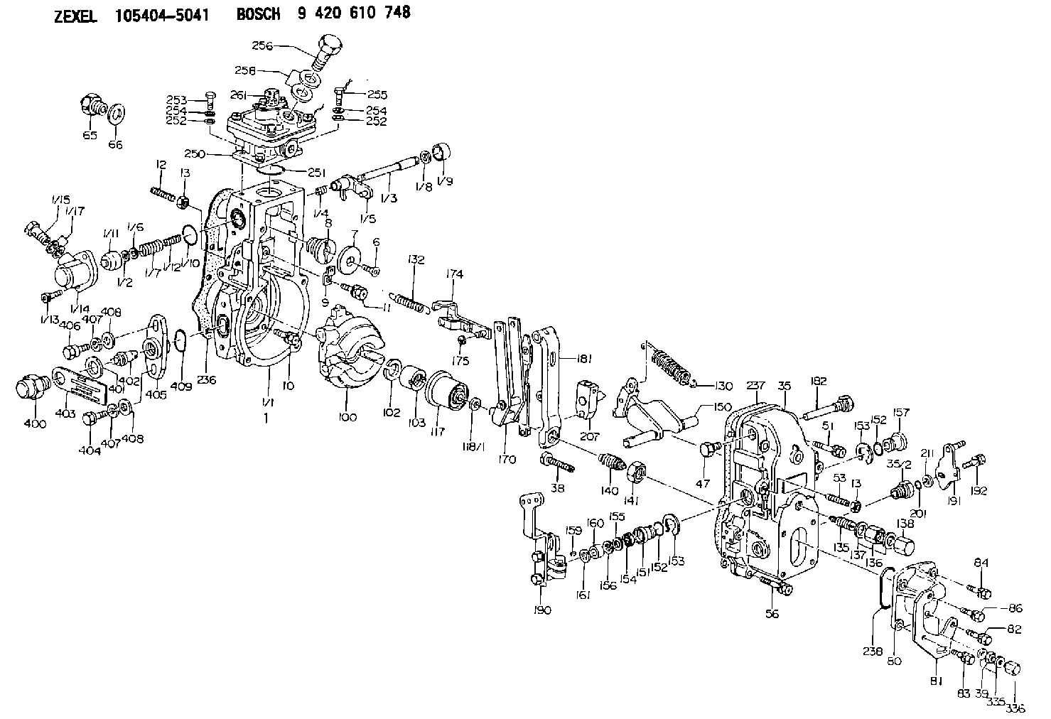
| 1. | [1] | 154620-0120 | GOVERNOR HOUSING |
| 1/1. | [1] | 154620-0020 | GOVERNOR HOUSING |
| 1/2. | [1] | 154620-5300 | PLAIN WASHER |
| 1/3. | [1] | 154620-6100 | LEVER SHAFT |
| 1/4. | [1] | 154621-0100 | COILED SPRING |
| 1/5. | [1] | 154620-2320 | CONTROL LEVER |
| 1/6. | [1] | 154620-5400 | SHIM |
| 1/7. | [1] | 154621-0200 | COILED SPRING |
| 1/8. | [1] | 154620-5500 | PLAIN WASHER |
| 1/9. | [1] | 154620-2400 | CAP |
| 1/10. | [1] | 154620-8200 | O-RING |
| 1/11. | [1] | 154620-7600 | BUSHING |
| 1/12. | [1] | 154621-0300 | COILED SPRING |
| 1/13. | [2] | 154620-4800 | BLEEDER SCREW |
| 1/14. | [1] | 154620-1200 | COVER |
| 1/15. | [1] | 029731-0120 | EYE BOLT |
| 1/17. | [2] | 029341-0110 | GASKET |
| 6. | [1] | 154621-4300 | BLEEDER SCREW |
| 7. | [1] | 154621-4100 | PLAIN WASHER |
| 8. | [1] | 154620-7900 | ADAPTOR |
| 9. | [1] | 154375-9020 | PLATE |
| 10. | [5] | 029010-6810 | BLEEDER SCREW |
| 11. | [1] | 020106-1840 | BLEEDER SCREW M6P1L18 |
| 12. | [1] | 154010-0100 | FLAT-HEAD SCREW |
| 13. | [2] | 154011-0100 | HEXAGON NUT |
| 13. | [2] | 154011-0100 | HEXAGON NUT |
| 35. | [1] | 154500-3020 | GOVERNOR COVER |
| 35/2. | [1] | 154321-0400 | BUSHING |
| 38. | [1] | 154031-3000 | FLAT-HEAD SCREW |
| 39. | [1] | 139206-0600 | UNION NUT |
| 47. | [1] | 154036-0300 | CAPSULE |
| 51. | [2] | 139006-7100 | BLEEDER SCREW |
| 53. | [1] | 154010-0200 | FLAT-HEAD SCREW |
| 56. | [4] | 020106-3840 | BLEEDER SCREW |
| 65. | [1] | 155404-5120 | STOPPING DEVICE |
| 66. | [1] | 026518-2240 | GASKET D21.9&18.2T1 |
| 80. | [1] | 154063-5100 | COVER |
| 81. | [1] | 154358-7200 | BRACKET |
| 82. | [1] | 029020-6260 | BLEEDER SCREW |
| 83. | [1] | 029020-6260 | BLEEDER SCREW |
| 84. | [1] | 020006-1640 | BLEEDER SCREW M6P1L16 4T |
| 86. | [1] | 020006-2040 | BLEEDER SCREW M6P1L20 4T |
| 100. | [1] | 154621-2120 | FLYWEIGHT ASSEMBLY |
| 102. | [1] | 029321-2020 | LOCKING WASHER |
| 103. | [1] | 029231-2030 | UNION NUT |
| 117. | [1] | 154123-0120 | SLIDING PIECE |
| 118/1. | [0] | 029311-0010 | SHIM D14&10.1T0.2 |
| 118/1. | [0] | 029311-0180 | SHIM D14&10.1T0.3 |
| 118/1. | [0] | 029311-0190 | SHIM D14&10.1T0.40 |
| 118/1. | [0] | 029311-0210 | SHIM D14&10.1T1 |
| 118/1. | [0] | 139410-0000 | SHIM D14.0&10.1T0.5 |
| 118/1. | [0] | 139410-0100 | SHIM D14.0&10.1T1.5 |
| 118/1. | [0] | 139410-3000 | SHIM D14&10.1T2.0 |
| 118/1. | [0] | 139410-3100 | SHIM D14&10.1T3.0 |
| 118/1. | [0] | 139410-3200 | SHIM D14&10.1T4.0 |
| 130. | [1] | 154150-0400 | GOVERNOR SPRING |
| 132. | [1] | 154154-5200 | COILED SPRING |
| 135. | [1] | 154158-0920 | HEADLESS SCREW |
| 136. | [1] | 154011-1700 | UNION NUT |
| 137. | [2] | 026512-1540 | GASKET D15.4&12.2T1.50 |
| 138. | [1] | 154159-1200 | CAP NUT |
| 140. | [1] | 154177-1020 | HEADLESS SCREW |
| 141. | [1] | 029201-6010 | UNION NUT |
| 150. | [1] | 154200-7020 | SWIVELLING LEVER |
| 151. | [1] | 154204-3000 | BUSHING |
| 152. | [2] | 029631-8020 | O-RING |
| 152. | [2] | 029631-8020 | O-RING |
| 153. | [2] | 016010-1640 | LOCKING WASHER |
| 153. | [2] | 016010-1640 | LOCKING WASHER |
| 154. | [1] | 139611-0000 | PACKING RING |
| 155. | [1] | 139411-0000 | SHIM |
| 156. | [0] | 029311-1070 | SHIM D16&11T0.5 |
| 157. | [1] | 154204-3100 | BUSHING |
| 159. | [1] | 025803-1310 | WOODRUFF KEY |
| 160. | [1] | 154206-2800 | BUSHING |
| 161. | [0] | 154206-0200 | PLAIN WASHER D19.5&11.2T1.0 |
| 170. | [1] | 154211-4420 | FORK LEVER |
| 174. | [1] | 154620-2520 | STRAP |
| 175. | [1] | 016010-0540 | LOCKING WASHER |
| 181. | [1] | 154236-4100 | TENSIONING LEVER |
| 182. | [1] | 154237-1100 | BEARING PIN |
| 190. | [1] | 154343-9220 | CONTROL LEVER |
| 191. | [1] | 154382-3720 | CONTROL LEVER |
| 192. | [1] | 020006-1840 | BLEEDER SCREW M6P1L18 |
| 201. | [1] | 029631-0030 | O-RING &9.8W2.3 |
| 207. | [1] | 154326-8520 | LEVER GROUP |
| 211. | [0] | 029311-0220 | SHIM D18&10.3T0.2 |
| 211B. | [0] | 029311-0230 | SHIM D18&10.3T0.5 |
| 236. | [1] | 154390-0000 | GASKET |
| 237. | [1] | 154390-0300 | GASKET |
| 238. | [1] | 029635-2020 | O-RING |
| 250. | [1] | 154421-2421 | MANIFOLD-PRESSURE COMP. |
| 251. | [1] | 016560-2610 | O-RING |
| 252. | [4] | 014020-6140 | PLAIN WASHER |
| 252. | [4] | 014020-6140 | PLAIN WASHER |
| 253. | [2] | 010006-1640 | BLEEDER SCREW M6P1L16 4T |
| 254. | [4] | 014110-6440 | LOCKING WASHER |
| 254. | [4] | 014110-6440 | LOCKING WASHER |
| 255. | [2] | 029010-6620 | BLEEDER SCREW |
| 256. | [1] | 029731-2040 | EYE BOLT |
| 258. | [2] | 029341-2140 | GASKET |
| 261. | [1] | 010506-0840 | FLAT-HEAD SCREW M6P1L8 |
| 335. | [2] | 026506-1040 | GASKET D9.9&6.2T1 |
| 336. | [1] | 154035-1600 | CAP NUT |
| 400. | [1] | 154620-8700 | CAPSULE |
| 401. | [1] | 154620-3100 | GASKET |
| 402. | [1] | 154620-8800 | BEARING PIN |
| 403. | [1] | 154620-8900 | PLATE |
| 404. | [1] | 010038-1840 | BLEEDER SCREW M8P1.25L18 |
| 405. | [1] | 154620-1500 | FLANGE BUSHING |
| 406. | [1] | 154620-4700 | BLEEDER SCREW |
| 407. | [2] | 014110-8440 | LOCKING WASHER |
| 407. | [2] | 014110-8440 | LOCKING WASHER |
| 408. | [2] | 014010-8140 | PLAIN WASHER D18&8.5T1.6 |
| 408. | [2] | 014010-8140 | PLAIN WASHER D18&8.5T1.6 |
| 409. | [1] | 154620-9000 | O-RING |
Cross reference number
Zexel num
Bosch num
Firm num
Name
Information:
Illustration 1 g00565418
4W-8471 Time Delay Relay
Use a 6V-7070 Digital Multimeter, a stopwatch, and a battery (8 volts to 40 volts) for this test.
Connect the positive lead of the voltage source to terminal (TD-4) of the time delay relay. Connect the negative lead to terminal (TD-3). If the test is done on an engine, the start/stop switch must be in the STOP position in order to power terminal (TD-6). All connections must be maintained until the tests are completed.
Use the multimeter to determine continuity. Compare the measurements to the following table.
Table 1
Terminals Relay Position
5-6 Closed
6-7 Open
Connect the positive lead of the voltage source to terminal (TD-1). If the time delay relay is tested on the engine do not leave the voltage source hooked to terminal (TD-1) for more than 60 seconds. The fuel shutoff solenoid will be energized. Use the multimeter to determine continuity. Compare the measurements to the following table.
Table 2
Terminals Relay Position
5-6 Open
6-7 Closed
Remove the positive lead of the voltage source from terminal (TD-1). Use the stopwatch to measure the time that is needed for the position of the relay to change. Use the multimeter to determine continuity. Compare the measurements to the following table.
Table 3
Terminals Delay Time of Relay Position
0 to 60 seconds 80 seconds or more
5-6 Open Closed
6-7 Closed Open Note: If a jumper is normally installed across terminals (TD-2) and (TD-3), the jumper must be removed before performing Step 5.
Connect the positive lead of the voltage source to terminal (TD-2). If the time delay relay is tested on the engine, do not leave the voltage source on terminal (TD-2) for more than 60 seconds. The fuel shutoff solenoid will be energized. Use the stopwatch to measure the time that is needed for the position of the relay to change. Use the multimeter to determine continuity. Compare the measurements to the following table.
Table 4
Terminals Delay Time of Relay Position
0 to 8 seconds 10 seconds or more
5-6 Closed Open
6-7 Open Closed
Remove the positive lead of the voltage source from terminal (TD-1). Use the stopwatch to measure the time that is needed for the position of the relay to change. Use the multimeter to determine continuity. Compare the measurements to the following table.
Table 5
Terminals Delay Time of Relay Position
0 to 60 seconds 80 seconds or more
5-6 Open Closed
6-7 Closed Open
Remove the voltage source from terminal (TD-4). Use the multimeter to determine continuity. Compare the measurements to the following table.
Table 6
Terminals Relay Position
5-6 Closed
6-7 Open