Information governor
BOSCH
9 420 610 747
9420610747
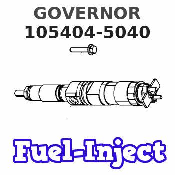
ZEXEL
105404-5040
1054045040
Rating:
Scheme ###:
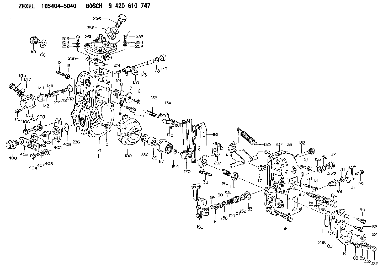
| 1. | [1] | 154620-0120 | GOVERNOR HOUSING |
| 1/1. | [1] | 154620-0020 | GOVERNOR HOUSING |
| 1/2. | [1] | 154620-5300 | PLAIN WASHER |
| 1/3. | [1] | 154620-6100 | LEVER SHAFT |
| 1/4. | [1] | 154621-0100 | COILED SPRING |
| 1/5. | [1] | 154620-2320 | CONTROL LEVER |
| 1/6. | [1] | 154620-5400 | SHIM |
| 1/7. | [1] | 154621-0200 | COILED SPRING |
| 1/8. | [1] | 154620-5500 | PLAIN WASHER |
| 1/9. | [1] | 154620-2400 | CAP |
| 1/10. | [1] | 154620-8200 | O-RING |
| 1/11. | [1] | 154620-7600 | BUSHING |
| 1/12. | [1] | 154621-0300 | COILED SPRING |
| 1/13. | [2] | 154620-4800 | BLEEDER SCREW |
| 1/14. | [1] | 154620-1200 | COVER |
| 1/15. | [1] | 029731-0120 | EYE BOLT |
| 1/17. | [2] | 029341-0110 | GASKET |
| 6. | [1] | 154621-4300 | BLEEDER SCREW |
| 7. | [1] | 154621-4100 | PLAIN WASHER |
| 8. | [1] | 154620-7900 | ADAPTOR |
| 9. | [1] | 154350-1800 | PLATE |
| 10. | [5] | 029010-6810 | BLEEDER SCREW |
| 11. | [1] | 020106-1640 | BLEEDER SCREW M6P1.0L14 |
| 12. | [1] | 154010-0100 | FLAT-HEAD SCREW |
| 13. | [2] | 154011-0100 | HEXAGON NUT |
| 13. | [2] | 154011-0100 | HEXAGON NUT |
| 35. | [1] | 154500-3020 | GOVERNOR COVER |
| 35/2. | [1] | 154321-0400 | BUSHING |
| 38. | [1] | 154031-3000 | FLAT-HEAD SCREW |
| 39. | [1] | 139206-0600 | UNION NUT |
| 47. | [1] | 154036-0300 | CAPSULE |
| 51. | [2] | 139006-7100 | BLEEDER SCREW |
| 53. | [1] | 154010-0200 | FLAT-HEAD SCREW |
| 56. | [4] | 020106-3840 | BLEEDER SCREW |
| 65. | [1] | 155404-5120 | STOPPING DEVICE |
| 66. | [1] | 026518-2240 | GASKET D21.9&18.2T1 |
| 80. | [1] | 154063-5100 | COVER |
| 81. | [1] | 154358-7200 | BRACKET |
| 82. | [1] | 029020-6260 | BLEEDER SCREW |
| 83. | [1] | 029020-6260 | BLEEDER SCREW |
| 84. | [1] | 020006-1640 | BLEEDER SCREW M6P1L16 4T |
| 86. | [1] | 020006-2040 | BLEEDER SCREW M6P1L20 4T |
| 100. | [1] | 154621-2120 | FLYWEIGHT ASSEMBLY |
| 102. | [1] | 029321-2020 | LOCKING WASHER |
| 103. | [1] | 029231-2030 | UNION NUT |
| 117. | [1] | 154123-0120 | SLIDING PIECE |
| 118/1. | [0] | 029311-0010 | SHIM D14&10.1T0.2 |
| 118/1. | [0] | 029311-0180 | SHIM D14&10.1T0.3 |
| 118/1. | [0] | 029311-0190 | SHIM D14&10.1T0.40 |
| 118/1. | [0] | 029311-0210 | SHIM D14&10.1T1 |
| 118/1. | [0] | 139410-0000 | SHIM D14.0&10.1T0.5 |
| 118/1. | [0] | 139410-0100 | SHIM D14.0&10.1T1.5 |
| 118/1. | [0] | 139410-3000 | SHIM D14&10.1T2.0 |
| 118/1. | [0] | 139410-3100 | SHIM D14&10.1T3.0 |
| 118/1. | [0] | 139410-3200 | SHIM D14&10.1T4.0 |
| 130. | [1] | 154150-0400 | GOVERNOR SPRING |
| 132. | [1] | 154154-2601 | COILED SPRING |
| 135. | [1] | 154158-0920 | HEADLESS SCREW |
| 136. | [1] | 154011-1700 | UNION NUT |
| 137. | [2] | 026512-1540 | GASKET D15.4&12.2T1.50 |
| 138. | [1] | 154159-1200 | CAP NUT |
| 140. | [1] | 154177-1020 | HEADLESS SCREW |
| 141. | [1] | 029201-6010 | UNION NUT |
| 150. | [1] | 154200-7020 | SWIVELLING LEVER |
| 151. | [1] | 154204-3000 | BUSHING |
| 152. | [2] | 029631-8020 | O-RING |
| 152. | [2] | 029631-8020 | O-RING |
| 153. | [2] | 016010-1640 | LOCKING WASHER |
| 153. | [2] | 016010-1640 | LOCKING WASHER |
| 154. | [1] | 139611-0000 | PACKING RING |
| 155. | [1] | 139411-0000 | SHIM |
| 156. | [0] | 029311-1090 | SHIM D16&11T0.3 |
| 157. | [1] | 154204-3100 | BUSHING |
| 159. | [1] | 025803-1310 | WOODRUFF KEY |
| 160. | [1] | 154206-2800 | BUSHING |
| 161. | [0] | 154206-0200 | PLAIN WASHER D19.5&11.2T1.0 |
| 170. | [1] | 154211-4420 | FORK LEVER |
| 174. | [1] | 154620-2520 | STRAP |
| 175. | [1] | 016010-0540 | LOCKING WASHER |
| 181. | [1] | 154236-4100 | TENSIONING LEVER |
| 182. | [1] | 154237-1100 | BEARING PIN |
| 190. | [1] | 154343-9220 | CONTROL LEVER |
| 191. | [1] | 154382-3720 | CONTROL LEVER |
| 192. | [1] | 020006-1840 | BLEEDER SCREW M6P1L18 |
| 201. | [1] | 029631-0030 | O-RING &9.8W2.3 |
| 207. | [1] | 154326-5120 | CONTROL LEVER |
| 211. | [0] | 029311-0220 | SHIM D18&10.3T0.2 |
| 211B. | [0] | 029311-0230 | SHIM D18&10.3T0.5 |
| 236. | [1] | 154390-0000 | GASKET |
| 237. | [1] | 154390-0300 | GASKET |
| 238. | [1] | 029635-2020 | O-RING |
| 250. | [1] | 154421-2421 | MANIFOLD-PRESSURE COMP. |
| 251. | [1] | 016560-2610 | O-RING |
| 252. | [4] | 014020-6140 | PLAIN WASHER |
| 252. | [4] | 014020-6140 | PLAIN WASHER |
| 253. | [2] | 010006-1640 | BLEEDER SCREW M6P1L16 4T |
| 254. | [4] | 014110-6440 | LOCKING WASHER |
| 254. | [4] | 014110-6440 | LOCKING WASHER |
| 255. | [2] | 029010-6620 | BLEEDER SCREW |
| 256. | [1] | 029731-2040 | EYE BOLT |
| 258. | [2] | 029341-2140 | GASKET |
| 261. | [1] | 010506-0840 | FLAT-HEAD SCREW M6P1L8 |
| 335. | [2] | 026506-1040 | GASKET D9.9&6.2T1 |
| 336. | [1] | 154035-1600 | CAP NUT |
| 400. | [1] | 154620-8700 | CAPSULE |
| 401. | [1] | 154620-3100 | GASKET |
| 402. | [1] | 154620-8800 | BEARING PIN |
| 403. | [1] | 154620-8900 | PLATE |
| 404. | [1] | 010038-1840 | BLEEDER SCREW M8P1.25L18 |
| 405. | [1] | 154620-1300 | FLANGE BUSHING |
| 406. | [1] | 154620-4700 | BLEEDER SCREW |
| 407. | [2] | 014110-8440 | LOCKING WASHER |
| 407. | [2] | 014110-8440 | LOCKING WASHER |
| 408. | [2] | 014010-8140 | PLAIN WASHER D18&8.5T1.6 |
| 408. | [2] | 014010-8140 | PLAIN WASHER D18&8.5T1.6 |
| 409. | [1] | 154620-9000 | O-RING |
Include in #1:
101402-3810
as GOVERNOR
Cross reference number
Zexel num
Bosch num
Firm num
Name
Information:
Illustration 1 g00565249The test for the water temperature contactor switch is a test for the temperature on the switch actuator and an electrical continuity test. This test will determine if the water temperature contactor switch is faulty and if the switch should be replaced. Use the 4C-6500 Digital Thermometer and the 4C-6500 Digital Thermometer for this test.
Install a probe from the 4C-6500 Digital Thermometer in the water manifold as close as possible to the water temperature contactor switch. Disconnect the connector for the water temperature contactor switch from the junction box. Note: Do not remove the water temperature contactor switch from the engine in order to conduct this test. The water temperature contactor switch uses the coolant flow and the coolant temperature in order to activate the switch at the actuation temperature.
When the water temperature contactor switch is disconnected from the junction box and the engine is stopped, check the continuity across the contact (WTS-3) and the common contact (WTS-2). Continuity should exist. This indicates that the circuit is closed across the contacts. Check the continuity across contact (WTS-1) and the common contact (WTS-2). Continuity should not exist. This indicates that the circuit is open across the contacts. If these conditions do not exist, the water temperature contactor switch is faulty and the switch needs to be replaced.
Start the engine. While the engine is running, place a load on the engine. Restrict the air flow to the engine. The engine should continue to run and the coolant temperature should increase to the actuation temperature of the water temperature contactor switch.
Observe the coolant temperature gauge in order to determine the temperature of the coolant when the actuation of the switch occurs. Compare the temperature on the gauge with the specifications for the water temperature contactor switch. The switch is actuated when the circuit across contacts (WTS-1) and (WTS-2) closes. The engine should shut down when the switch is actuated. This activates the protection system.
The actuation of the water temperature contactor switch may not occur when the temperature of the coolant is greater than the maximum value for the actuation temperature of the switch. Immediately reduce the load that is on the engine and remove the restriction to the air inlet. Allow the engine to run at idle until the temperature of the coolant returns to normal before you stop the engine.
The actual temperature of the coolant may not have been within the specifications of the water temperature contactor switch at the time of actuation. The switch is faulty and the switch needs to be replaced. Actuation might not occur when the temperature of the coolant is at the maximum. The switch is faulty and the switch needs to be replaced.