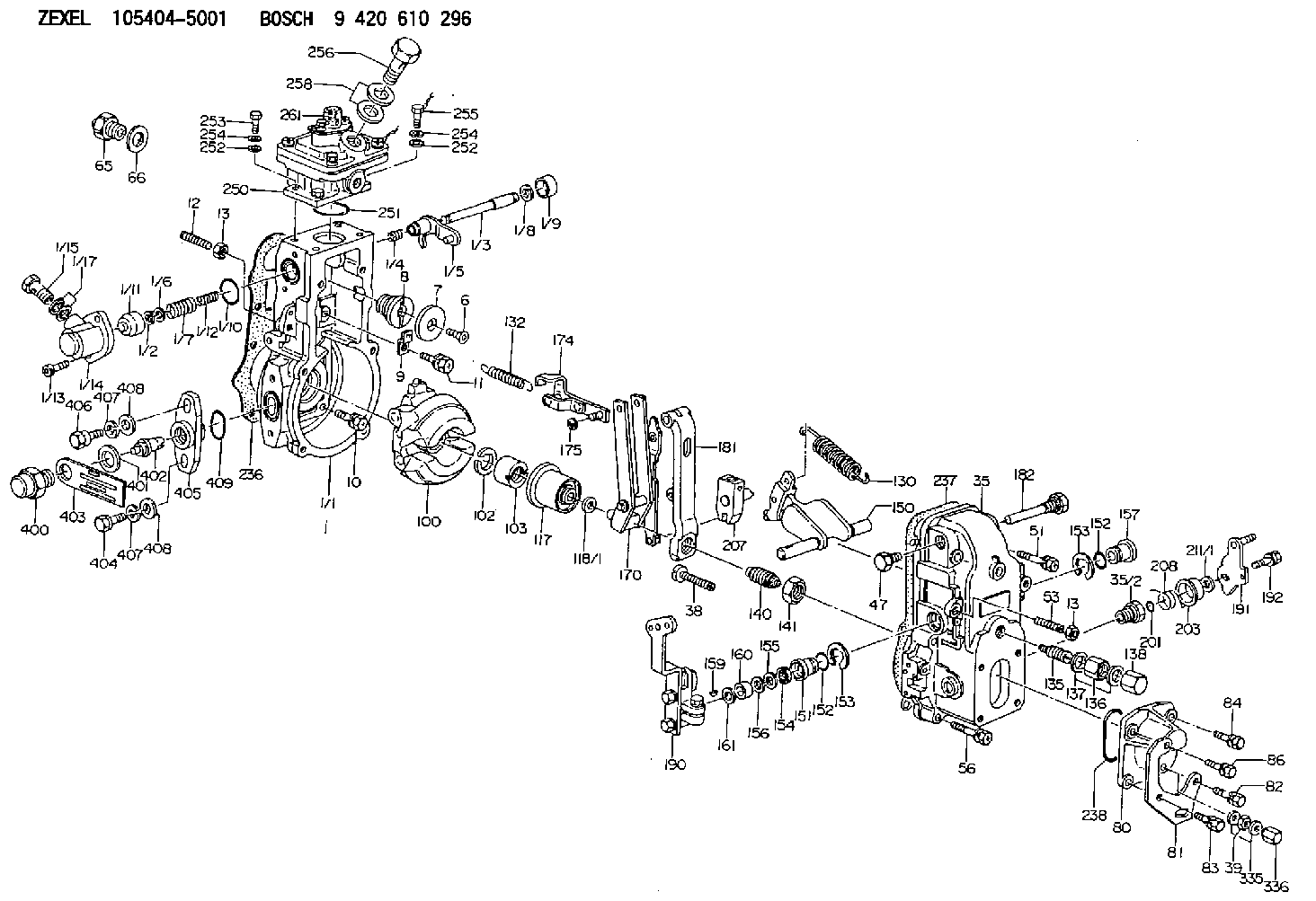
Information governor
BOSCH
9 420 610 296
9420610296
ZEXEL
105404-5001
1054045001
Rating:
Scheme ###:
| 1. | [1] | 154620-0120 | GOVERNOR HOUSING |
| 1/1. | [1] | 154620-0020 | GOVERNOR HOUSING |
| 1/2. | [1] | 154620-5300 | PLAIN WASHER |
| 1/3. | [1] | 154620-6100 | LEVER SHAFT |
| 1/4. | [1] | 154621-0100 | COILED SPRING |
| 1/5. | [1] | 154620-2320 | CONTROL LEVER |
| 1/6. | [1] | 154620-5400 | SHIM |
| 1/7. | [1] | 154621-0200 | COILED SPRING |
| 1/8. | [1] | 154620-5500 | PLAIN WASHER |
| 1/9. | [1] | 154620-2400 | CAP |
| 1/10. | [1] | 154620-8200 | O-RING |
| 1/11. | [1] | 154620-7600 | BUSHING |
| 1/12. | [1] | 154621-0300 | COILED SPRING |
| 1/13. | [2] | 154620-4800 | BLEEDER SCREW |
| 1/14. | [1] | 154620-1200 | COVER |
| 1/15. | [1] | 029731-0120 | EYE BOLT |
| 1/17. | [2] | 029341-0110 | GASKET |
| 6. | [1] | 154621-4300 | BLEEDER SCREW |
| 7. | [1] | 154621-4100 | PLAIN WASHER |
| 8. | [1] | 154620-7900 | ADAPTOR |
| 9. | [1] | 154350-1800 | PLATE |
| 10. | [5] | 029010-6810 | BLEEDER SCREW |
| 11. | [1] | 020106-1640 | BLEEDER SCREW M6P1.0L14 |
| 12. | [1] | 154010-0100 | FLAT-HEAD SCREW |
| 13. | [2] | 154011-0100 | HEXAGON NUT |
| 13. | [2] | 154011-0100 | HEXAGON NUT |
| 35. | [1] | 154500-3020 | GOVERNOR COVER |
| 35/2. | [1] | 154321-0400 | BUSHING |
| 38. | [1] | 154031-3000 | FLAT-HEAD SCREW |
| 39. | [1] | 139206-0600 | UNION NUT |
| 47. | [1] | 154036-0300 | CAPSULE |
| 51. | [2] | 139006-7100 | BLEEDER SCREW |
| 53. | [1] | 154010-0200 | FLAT-HEAD SCREW |
| 56. | [4] | 020106-3840 | BLEEDER SCREW |
| 65. | [1] | 155404-5120 | STOPPING DEVICE |
| 66. | [1] | 026518-2240 | GASKET D21.9&18.2T1 |
| 80. | [1] | 154063-5100 | COVER |
| 81. | [1] | 154358-7200 | BRACKET |
| 82. | [1] | 029020-6260 | BLEEDER SCREW |
| 83. | [1] | 029020-6260 | BLEEDER SCREW |
| 84. | [1] | 020006-1640 | BLEEDER SCREW M6P1L16 4T |
| 86. | [1] | 020006-2040 | BLEEDER SCREW M6P1L20 4T |
| 100. | [1] | 154621-2120 | FLYWEIGHT ASSEMBLY |
| 102. | [1] | 029321-2020 | LOCKING WASHER |
| 103. | [1] | 029231-2030 | UNION NUT |
| 117. | [1] | 154123-0120 | SLIDING PIECE |
| 118/1. | [0] | 029311-0010 | SHIM D14&10.1T0.2 |
| 118/1. | [0] | 029311-0180 | SHIM D14&10.1T0.3 |
| 118/1. | [0] | 029311-0190 | SHIM D14&10.1T0.40 |
| 118/1. | [0] | 029311-0210 | SHIM D14&10.1T1 |
| 118/1. | [0] | 139410-0000 | SHIM D14.0&10.1T0.5 |
| 118/1. | [0] | 139410-0100 | SHIM D14.0&10.1T1.5 |
| 118/1. | [0] | 139410-3000 | SHIM D14&10.1T2.0 |
| 118/1. | [0] | 139410-3100 | SHIM D14&10.1T3.0 |
| 118/1. | [0] | 139410-3200 | SHIM D14&10.1T4.0 |
| 130. | [1] | 154150-0400 | GOVERNOR SPRING |
| 132. | [1] | 154154-2601 | COILED SPRING |
| 135. | [1] | 154158-0920 | HEADLESS SCREW |
| 136. | [1] | 154011-1700 | UNION NUT |
| 137. | [2] | 026512-1540 | GASKET D15.4&12.2T1.50 |
| 138. | [1] | 154159-1200 | CAP NUT |
| 140. | [1] | 154177-1020 | HEADLESS SCREW |
| 141. | [1] | 029201-6010 | UNION NUT |
| 150. | [1] | 154200-7020 | SWIVELLING LEVER |
| 151. | [1] | 154204-3000 | BUSHING |
| 152. | [2] | 029631-8020 | O-RING |
| 152. | [2] | 029631-8020 | O-RING |
| 153. | [2] | 016010-1640 | LOCKING WASHER |
| 153. | [2] | 016010-1640 | LOCKING WASHER |
| 154. | [1] | 139611-0000 | PACKING RING |
| 155. | [1] | 139411-0000 | SHIM |
| 156. | [0] | 029311-1070 | SHIM D16&11T0.5 |
| 157. | [1] | 154204-3100 | BUSHING |
| 159. | [1] | 025803-1310 | WOODRUFF KEY |
| 160. | [1] | 154206-2800 | BUSHING |
| 161. | [0] | 154206-0200 | PLAIN WASHER D19.5&11.2T1.0 |
| 170. | [1] | 154211-4420 | FORK LEVER |
| 174. | [1] | 154620-2520 | STRAP |
| 175. | [1] | 016010-0540 | LOCKING WASHER |
| 181. | [1] | 154236-4100 | TENSIONING LEVER |
| 182. | [1] | 154237-1100 | BEARING PIN |
| 190. | [1] | 154343-9220 | CONTROL LEVER |
| 191. | [1] | 154382-3720 | CONTROL LEVER |
| 192. | [1] | 020006-1840 | BLEEDER SCREW M6P1L18 |
| 201. | [1] | 029631-0030 | O-RING &9.8W2.3 |
| 203. | [1] | 154322-0100 | CAP |
| 207. | [1] | 154326-8520 | LEVER GROUP |
| 208. | [1] | 154327-7300 | COILED SPRING |
| 211/1. | [0] | 029311-0520 | SHIM D20.8&10.3T0.2 |
| 211/1. | [0] | 029311-0530 | SHIM D20.8&10.3T0.25 |
| 211/1. | [0] | 029311-0540 | SHIM D20.8&10.3T0.3 |
| 211/1. | [0] | 029311-0550 | SHIM D20.8&10.3T0.35 |
| 211/1. | [0] | 029311-0560 | SHIM D20.8&10.3T0.4 |
| 211/1. | [0] | 029311-0570 | SHIM D20.8&10.3T0.5 |
| 236. | [1] | 154390-0000 | GASKET |
| 237. | [1] | 154390-0300 | GASKET |
| 238. | [1] | 029635-2020 | O-RING |
| 250. | [1] | 154421-2421 | MANIFOLD-PRESSURE COMP. |
| 251. | [1] | 016560-2610 | O-RING |
| 252. | [4] | 014020-6140 | PLAIN WASHER |
| 252. | [4] | 014020-6140 | PLAIN WASHER |
| 253. | [2] | 010006-1640 | BLEEDER SCREW M6P1L16 4T |
| 254. | [4] | 014110-6440 | LOCKING WASHER |
| 254. | [4] | 014110-6440 | LOCKING WASHER |
| 255. | [2] | 029010-6620 | BLEEDER SCREW |
| 256. | [1] | 029731-2040 | EYE BOLT |
| 258. | [2] | 029341-2140 | GASKET |
| 261. | [1] | 010506-0840 | FLAT-HEAD SCREW M6P1L8 |
| 335. | [2] | 026506-1040 | GASKET D9.9&6.2T1 |
| 336. | [1] | 154035-1600 | CAP NUT |
| 400. | [1] | 154620-8700 | CAPSULE |
| 401. | [1] | 154620-3100 | GASKET |
| 402. | [1] | 154620-8800 | BEARING PIN |
| 403. | [1] | 154620-8900 | PLATE |
| 404. | [1] | 010038-1840 | BLEEDER SCREW M8P1.25L18 |
| 405. | [1] | 154620-1500 | FLANGE BUSHING |
| 406. | [1] | 154620-4700 | BLEEDER SCREW |
| 407. | [2] | 014110-8440 | LOCKING WASHER |
| 407. | [2] | 014110-8440 | LOCKING WASHER |
| 408. | [2] | 014010-8140 | PLAIN WASHER D18&8.5T1.6 |
| 408. | [2] | 014010-8140 | PLAIN WASHER D18&8.5T1.6 |
| 409. | [1] | 154620-9000 | O-RING |
Cross reference number
Zexel num
Bosch num
Firm num
Name
Information:
Test 1 - Overspeed Switch (OS)
Table 1
Overspeed Switch (OS)
Step Engine RPM Action Correct Result
A 25 + 5 rpm less than 75% Overspeed Verify rpm Press the 75% Verify button No engine shutdown
B 25 + 5 rpm more than 75% Overspeed Verify rpm Press the 75% Verify button Air and fuel shutoff
C Manually reset the air shutoff lever at the top of the air inlet, if equipped. Press the ESS reset button. Test 2 - Emergency Stop Switch (ES)
Table 2
Emergency Stop Switch (ES)
Step Engine RPM Action Correct Result
A Any rpm above the crank terminate rpm Press the push button for the emergency stop switch Air and fuel shutoff
B Manually reset the air shutoff lever at the top of the air inlet, if equipped. Turn ES switch in the dirction that is shown on the face of the push button in order to reset the switch. Test 3 - Normal Stop Switch (NSS)
Table 3
Normal Stop Switch (NSS)
Step Engine RPM Action Correct Result
A Any rpm above the crank terminate rpm Push the normal stop switch (NSS) Fuel shutoff Test 4 - Water Temperature Contactor Switch
Table 4
Water Temperature Contactor Switch (WTS)
Step Engine RPM Action Correct Result
A Any rpm above the crank terminate rpm Place a jumper across terminals TS-2 and TS-7. Fuel shutoff
B Remove the jumper from terminals TS-2 and TS-7. Test 5 - Oil Pressure Switch (OPS1)
Table 5
Oil Pressure Switch (OPS1)
Step Engine RPM Action Correct Result
A Any rpm above the crank terminate rpm Place a jumper across terminals OPS1-1 and OPS1-3. Fuel shutoff
B Remove the jumper from terminals OPS1-1 and OPS1-3. Test 6 - Oil Pressure Switch (OPS2)
Table 6
Oil Pressure Switch (OPS2)
Step Engine RPM Action Correct Result
A 25 + 5 rpm less than the setting for the oil step speed Place a jumper across terminals OPS2-1 and OPS2-3. No engine shutdown.
B 25 + 5 rpm more than the setting for the oil step speed Place a jumper across terminals OPS2-1 and OPS2-3. Fuel shutoff 9 seconds after the oil step speed is reached.
C Remove the jumper from across terminals OPS2-1 and OPS2-3.