Information governor
BOSCH
9 420 612 350
9420612350
ZEXEL
105402-2390
1054022390
MITSUBISHI
ME727270
me727270
Rating:
Scheme ###:
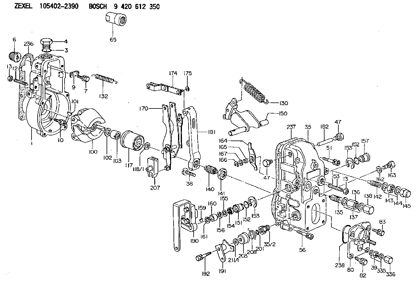
| 1. | [1] | 154000-6300 | GOVERNOR HOUSING |
| 3. | [1] | 029632-5070 | O-RING |
| 4. | [1] | 154007-2900 | CAPSULE |
| 6. | [1] | 154007-0200 | ADAPTOR |
| 7. | [1] | 020018-1840 | BLEEDER SCREW M8P1.25L18 |
| 9. | [1] | 154350-1900 | PLATE |
| 10. | [6] | 029010-6810 | BLEEDER SCREW |
| 12. | [1] | 154010-0100 | FLAT-HEAD SCREW |
| 13. | [2] | 154011-0100 | HEXAGON NUT |
| 13. | [2] | 154011-0100 | HEXAGON NUT |
| 35. | [1] | 154500-1220 | GOVERNOR COVER |
| 35/2. | [1] | 154321-0400 | BUSHING |
| 38. | [1] | 154031-2400 | FLAT-HEAD SCREW |
| 39. | [1] | 139206-0600 | UNION NUT |
| 47. | [2] | 154036-0300 | CAPSULE |
| 47. | [2] | 154036-0300 | CAPSULE |
| 51. | [2] | 020106-5040 | BLEEDER SCREW |
| 53. | [1] | 154010-0200 | FLAT-HEAD SCREW |
| 56. | [4] | 020106-3840 | BLEEDER SCREW |
| 65. | [1] | 154050-6120 | STOPPING DEVICE |
| 80. | [1] | 154063-5420 | COVER |
| 82. | [2] | 029020-6210 | BLEEDER SCREW |
| 83. | [2] | 020006-1640 | BLEEDER SCREW M6P1L16 4T |
| 100. | [1] | 154101-0020 | FLYWEIGHT ASSEMBLY |
| 101. | [1] | 025803-1610 | WOODRUFF KEY |
| 102. | [1] | 029321-2020 | LOCKING WASHER |
| 103. | [1] | 029231-2030 | UNION NUT |
| 117. | [1] | 154123-2320 | SLIDING PIECE |
| 118/1. | [0] | 029311-0010 | SHIM D14&10.1T0.2 |
| 118/1. | [0] | 029311-0180 | SHIM D14&10.1T0.3 |
| 118/1. | [0] | 029311-0190 | SHIM D14&10.1T0.40 |
| 118/1. | [0] | 029311-0210 | SHIM D14&10.1T1 |
| 118/1. | [0] | 139410-0000 | SHIM D14.0&10.1T0.5 |
| 118/1. | [0] | 139410-0100 | SHIM D14.0&10.1T1.5 |
| 118/1. | [0] | 139410-3000 | SHIM D14&10.1T2.0 |
| 118/1. | [0] | 139410-3100 | SHIM D14&10.1T3.0 |
| 118/1. | [0] | 139410-3200 | SHIM D14&10.1T4.0 |
| 130. | [1] | 154150-2900 | GOVERNOR SPRING |
| 132. | [1] | 154154-0500 | COILED SPRING |
| 135. | [1] | 154158-1020 | HEADLESS SCREW |
| 136. | [1] | 154011-1700 | UNION NUT |
| 137. | [2] | 026512-1540 | GASKET D15.4&12.2T1.50 |
| 138. | [1] | 154159-1200 | CAP NUT |
| 140. | [1] | 154177-0320 | HEADLESS SCREW |
| 141. | [1] | 029201-6010 | UNION NUT |
| 142. | [1] | 154242-1220 | HEADLESS SCREW |
| 143. | [1] | 029201-6150 | UNION NUT |
| 144. | [2] | 026516-2040 | GASKET D19.9&16.2T1 |
| 145. | [1] | 154159-1100 | CAP NUT |
| 150. | [1] | 154200-7020 | SWIVELLING LEVER |
| 151. | [1] | 154204-3000 | BUSHING |
| 152. | [2] | 029631-8020 | O-RING |
| 152. | [2] | 029631-8020 | O-RING |
| 153. | [2] | 016010-1640 | LOCKING WASHER |
| 153. | [2] | 016010-1640 | LOCKING WASHER |
| 154. | [1] | 139611-0000 | PACKING RING |
| 155. | [1] | 139411-0000 | SHIM |
| 156. | [0] | 029311-1070 | SHIM D16&11T0.5 |
| 157. | [1] | 154204-3100 | BUSHING |
| 159. | [1] | 025803-1310 | WOODRUFF KEY |
| 160. | [1] | 154206-2800 | BUSHING |
| 161. | [0] | 154206-0200 | PLAIN WASHER D19.5&11.2T1.0 |
| 162. | [1] | 029331-0240 | GASKET |
| 163. | [1] | 154401-2700 | BLEEDER SCREW |
| 164. | [1] | 154243-0320 | CONTROL LEVER |
| 165. | [1] | 154327-2000 | COILED SPRING |
| 166. | [1] | 016010-0710 | LOCKING WASHER |
| 167. | [1] | 029310-8020 | PLAIN WASHER D15&8.4T0.3 |
| 170. | [1] | 154217-3720 | FORK LEVER |
| 174. | [1] | 154230-3920 | STRAP |
| 175. | [1] | 016010-0540 | LOCKING WASHER |
| 181. | [1] | 154236-3320 | TENSIONING LEVER |
| 182. | [1] | 154237-0100 | BEARING PIN |
| 190. | [1] | 154347-2920 | CONTROL LEVER |
| 191. | [1] | 154380-6020 | CONTROL LEVER |
| 192. | [1] | 020006-3240 | BLEEDER SCREW |
| 201. | [1] | 029631-0030 | O-RING &9.8W2.3 |
| 203. | [1] | 154322-0100 | CAP |
| 207. | [1] | 154326-5720 | CONTROL LEVER |
| 208. | [1] | 154327-8700 | COILED SPRING |
| 211/1. | [0] | 029311-0520 | SHIM D20.8&10.3T0.2 |
| 211/1. | [0] | 029311-0530 | SHIM D20.8&10.3T0.25 |
| 211/1. | [0] | 029311-0540 | SHIM D20.8&10.3T0.3 |
| 211/1. | [0] | 029311-0550 | SHIM D20.8&10.3T0.35 |
| 211/1. | [0] | 029311-0560 | SHIM D20.8&10.3T0.4 |
| 211/1. | [0] | 029311-0570 | SHIM D20.8&10.3T0.5 |
| 236. | [1] | 154390-0000 | GASKET |
| 237. | [1] | 154390-0300 | GASKET |
| 238. | [1] | 029635-2020 | O-RING |
| 335. | [2] | 026506-1040 | GASKET D9.9&6.2T1 |
| 336. | [1] | 154035-1600 | CAP NUT |
Cross reference number
Zexel num
Bosch num
Firm num
Name
105402-2390
ME727270 MITSUBISHI
GOVERNOR
K 14JB MECHANICAL GOVERNOR GOV RSV GOV
K 14JB MECHANICAL GOVERNOR GOV RSV GOV
Information:
5N5930 Fuel Injection Lines Group
(1) Remove former fuel injection lines (1) from each fuel injection pump to the adapters in the base of the valve mechanism cover. Remove the cover from the base. Remove the through-the-base adapter for each set of fuel lines. Put an 8M4437 Seal on each 1W6777 Adapter (2) and install the adapters in each bore where the adapters were removed. Use engine oil as a lubricant on the seals. Fasten the adapters to the cover base with the former nuts and two 5N5365 Locks on each. Connect former fuel lines (3) to adapters (2) and to the injector nozzles. (2) Install 2W2496 Bracket (4) and 2W2495 Bracket (5) where the former brackets were removed. Put a 5P9267 Seal on each injector pump and put a 2W2500 Washer (6) and 6V6579 Seal (7) on each adapter (2). Loosely install the fuel injection line assemblies that follow: 1W6318 (8), 1W6316 (9), 1W6313 (10), 1W6317 (11), 1W6315 (12), 1W6312 (13), 1W6314 (14) and 1W6311 (15). Tighten fuel injection line nuts (16) on each fuel line to 41 7 N m (30 5 lb.ft.) before cover nuts (17) are tightened. If the fuel lines have metal tags for part number identification, remove the tags before installation. Fasten tubes (8), (9), (12) and (15) together on the left side with four 2W2492 Clamps (18), 2W2493 Clamps and 310216 Bolts. Fasten the fuel lines to brackets (4) and (5) with 2W2492 Clamps (19), 2W2493 Clamps, 2W2494 Spacers, 1D4533 Bolts and 3B4504 Lockwashers. Fasten the fuel injection lines together on the right side with 2W2492 Clamps (20), 2W2493 Clamps and 310216 Bolts. Install four 2W2498 and 2W2499 Clamps on tubes (12) and (14) with 6V5370 Screws as shown.2W1788 Fuel Lines Drain Group
(1) Install a 9L8496 Tee (1) on each fuel line adapter (2). Install six 5N5940 Tube Assemblies (3) between tees (1) as shown. Install two 9L8492 Plugs (4). Install 2W3092 Tube Assembly (5), 2W3091 Tube Assembly (6) and 9L8557 Tee (7). Install 4M5317 Bushing (8) and 8B1931 Bushing (9) in 2N9768 Switch (10). Install 9L8496 Tee (11) in bushing (9). Fasten switch (10) to 2W3089 Bracket Assembly (12) with two S1616 Bolts, four 5P537 Washers and two 9S8750 Nuts. Fasten bracket (12) to the side of the engine with two S1594 Bolts, 5M2894 Washers and 9S8752 Nuts. Connect 2W3935 Tube Assembly (13) to tees (7) and (11). Install a 9L8492 Plug in the other side of tee (11). Install 5K9243 Elbow (14) in bushing (8). Connect 5N7739 Tube Assembly (15) to elbow (14). Fasten tubes (13) and (15) to existing bolts with 2B2404 Clips (16).