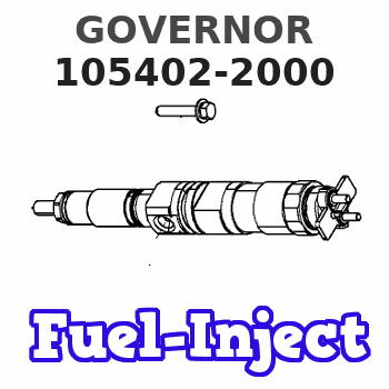
Information governor
BOSCH
F 019 Z2F 436
f019z2f436
ZEXEL
105402-2000
1054022000
MITSUBISHI
ME018057
me018057
Rating:
Scheme ###:
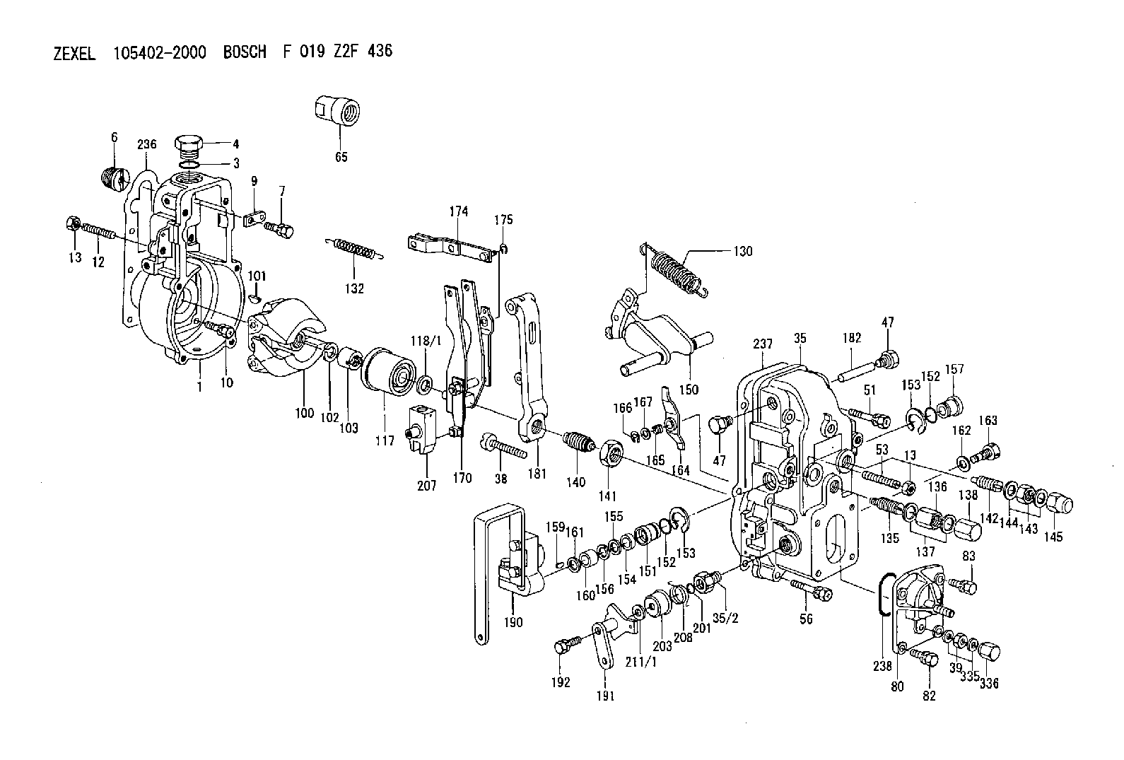
| 1. | [1] | 154000-6300 | GOVERNOR HOUSING |
| 3. | [1] | 029632-5070 | O-RING |
| 4. | [1] | 154007-2900 | CAPSULE |
| 6. | [1] | 154007-0200 | ADAPTOR |
| 7. | [1] | 020018-1840 | BLEEDER SCREW M8P1.25L18 |
| 9. | [1] | 154350-1900 | PLATE |
| 10. | [6] | 029010-6810 | BLEEDER SCREW |
| 12. | [1] | 154010-0100 | FLAT-HEAD SCREW |
| 13. | [2] | 154011-0100 | HEXAGON NUT |
| 13. | [2] | 154011-0100 | HEXAGON NUT |
| 35. | [1] | 154500-1220 | GOVERNOR COVER |
| 35/2. | [1] | 154321-0400 | BUSHING |
| 38. | [1] | 154031-2400 | FLAT-HEAD SCREW |
| 39. | [1] | 139206-0600 | UNION NUT |
| 47. | [2] | 154036-0300 | CAPSULE |
| 47. | [2] | 154036-0300 | CAPSULE |
| 51. | [2] | 020106-5040 | BLEEDER SCREW |
| 53. | [1] | 154010-0200 | FLAT-HEAD SCREW |
| 56. | [4] | 020106-3840 | BLEEDER SCREW |
| 65. | [1] | 154050-6120 | STOPPING DEVICE |
| 80. | [1] | 154063-5420 | COVER |
| 82. | [2] | 029020-6210 | BLEEDER SCREW |
| 83. | [2] | 020006-1640 | BLEEDER SCREW M6P1L16 4T |
| 100. | [1] | 154101-0020 | FLYWEIGHT ASSEMBLY |
| 101. | [1] | 025803-1610 | WOODRUFF KEY |
| 102. | [1] | 029321-2020 | LOCKING WASHER |
| 103. | [1] | 029231-2030 | UNION NUT |
| 117. | [1] | 154123-2320 | SLIDING PIECE |
| 118/1. | [0] | 029311-0010 | SHIM D14&10.1T0.2 |
| 118/1. | [0] | 029311-0180 | SHIM D14&10.1T0.3 |
| 118/1. | [0] | 029311-0190 | SHIM D14&10.1T0.40 |
| 118/1. | [0] | 029311-0210 | SHIM D14&10.1T1 |
| 118/1. | [0] | 139410-0000 | SHIM D14.0&10.1T0.5 |
| 118/1. | [0] | 139410-0100 | SHIM D14.0&10.1T1.5 |
| 118/1. | [0] | 139410-3000 | SHIM D14&10.1T2.0 |
| 118/1. | [0] | 139410-3100 | SHIM D14&10.1T3.0 |
| 118/1. | [0] | 139410-3200 | SHIM D14&10.1T4.0 |
| 130. | [1] | 154150-2900 | GOVERNOR SPRING |
| 132. | [1] | 154154-0500 | COILED SPRING |
| 135. | [1] | 154158-1020 | HEADLESS SCREW |
| 136. | [1] | 154011-1700 | UNION NUT |
| 137. | [2] | 026512-1540 | GASKET D15.4&12.2T1.50 |
| 138. | [1] | 154159-1200 | CAP NUT |
| 140. | [1] | 154177-0320 | HEADLESS SCREW |
| 141. | [1] | 029201-6010 | UNION NUT |
| 142. | [1] | 154242-1220 | HEADLESS SCREW |
| 143. | [1] | 029201-6150 | UNION NUT |
| 144. | [2] | 026516-2040 | GASKET D19.9&16.2T1 |
| 145. | [1] | 154159-1100 | CAP NUT |
| 150. | [1] | 154200-7020 | SWIVELLING LEVER |
| 151. | [1] | 154204-4300 | BUSHING |
| 152. | [2] | 029631-8020 | O-RING |
| 152. | [2] | 029631-8020 | O-RING |
| 153. | [2] | 016010-1640 | LOCKING WASHER |
| 153. | [2] | 016010-1640 | LOCKING WASHER |
| 154. | [1] | 139611-0000 | PACKING RING |
| 155. | [1] | 139411-0000 | SHIM |
| 156. | [0] | 029311-1070 | SHIM D16&11T0.5 |
| 157. | [1] | 154204-4400 | BUSHING |
| 159. | [1] | 025803-1310 | WOODRUFF KEY |
| 160. | [1] | 154206-2800 | BUSHING |
| 161. | [0] | 154206-0200 | PLAIN WASHER D19.5&11.2T1.0 |
| 162. | [1] | 029331-0240 | GASKET |
| 163. | [1] | 154401-2700 | BLEEDER SCREW |
| 164. | [1] | 154243-0320 | CONTROL LEVER |
| 165. | [1] | 154327-2000 | COILED SPRING |
| 166. | [1] | 016010-0710 | LOCKING WASHER |
| 167. | [1] | 029310-8020 | PLAIN WASHER D15&8.4T0.3 |
| 170. | [1] | 154217-3720 | FORK LEVER |
| 174. | [1] | 154230-3920 | STRAP |
| 175. | [1] | 016010-0540 | LOCKING WASHER |
| 181. | [1] | 154236-3320 | TENSIONING LEVER |
| 182. | [1] | 154237-0100 | BEARING PIN |
| 190. | [1] | 154347-2920 | CONTROL LEVER |
| 191. | [1] | 154366-3720 | CONTROL LEVER |
| 192. | [1] | 020006-3540 | BLEEDER SCREW |
| 201. | [1] | 029631-0030 | O-RING &9.8W2.3 |
| 203. | [1] | 154322-0100 | CAP |
| 207. | [1] | 154326-8920 | LEVER GROUP |
| 208. | [1] | 154327-7700 | COILED SPRING |
| 211/1. | [0] | 029311-0520 | SHIM D20.8&10.3T0.2 |
| 211/1. | [0] | 029311-0530 | SHIM D20.8&10.3T0.25 |
| 211/1. | [0] | 029311-0540 | SHIM D20.8&10.3T0.3 |
| 211/1. | [0] | 029311-0550 | SHIM D20.8&10.3T0.35 |
| 211/1. | [0] | 029311-0560 | SHIM D20.8&10.3T0.4 |
| 211/1. | [0] | 029311-0570 | SHIM D20.8&10.3T0.5 |
| 236. | [1] | 154390-0000 | GASKET |
| 237. | [1] | 154390-0300 | GASKET |
| 238. | [1] | 029635-2020 | O-RING |
| 335. | [2] | 026506-1040 | GASKET D9.9&6.2T1 |
| 336. | [1] | 154035-1600 | CAP NUT |
Include in #1:
101492-1100
as GOVERNOR
Cross reference number
Zexel num
Bosch num
Firm num
Name
105402-2000
F 019 Z2F 436
ME018057 MITSUBISHI
GOVERNOR
* K
* K
Information:
1. Remove four bolts (1) and the washers that hold the oil pump in position. Remove the oil pump. The following steps are for the installation of the oil pump.2. Be sure the mounting surfaces for the oil pump are thoroughly clean.3. Install the oil pump in the reverse order of removal.End By:a. install oil panDisassemble & Assemble Oil Pump
Start By:a. remove oil pump 1. Remove the bolts and washers that hold oil pick-up tube assembly (1) to the oil pump. Remove the oil pick-up tube assembly and gasket.2. Remove the bolts and washers that hold oil discharge tube assembly (2) to the oil pump. Remove the oil discharge tube assembly and the O-ring seal. 3. Remove the idler gear from the oil pump.4. Remove bolt (6), and remove relief valve spring (8) with relief valve (7).5. Use Tooling (A) to remove input gear (4).
Before removing the input shaft and gear from the pump body, be sure there are no burrs on the input shaft. Burrs on the input shaft may scratch and damage the pump body.
6. Remove bolts (5), and separate the pump body. Remove input shaft and gear (3) from the pump body. Remove the driven gear from the pump body. The following steps are for the assembly of the oil pump.7. Be sure all parts of the oil pump are thoroughly clean prior to assembly. Apply clean engine oil on the internal parts of the oil pump. Before pressing input gear (4) onto input shaft (3), be sure to install bolt (5). Bolt (5) is positioned under the input gear.8. Put the input gear and shaft (3) in the pump body. Press the input gear (4) onto the input shaft until ti is even with the end of the shaft. Put the driven gear in position in the pump body.9. Put the pump bodies together, and install bolts (5). Install the idler gear.10. Install relief valve spring (8) and relief valve (7) in the pump body. Install bolt (6).11. Check the condition of the O-ring seal used in oil discharge tube assembly (2). If the seal is damaged, use a new part for replacement. Install the O-ring seal in the tube assembly. Install the oil discharge tube assembly and the bolts and washers that hold it.12. Check the condition of the gasket used in oil pick-up tube assembly (1). If the gasket is damaged, use a new part for replacement. Install the gasket, the oil discharge tube assembly and the bolts and washers that hold it.End By:a. install oil pump
Have questions with 105402-2000?
Group cross 105402-2000 ZEXEL
Mitsubishi
105402-2000
F 019 Z2F 436
ME018057
GOVERNOR