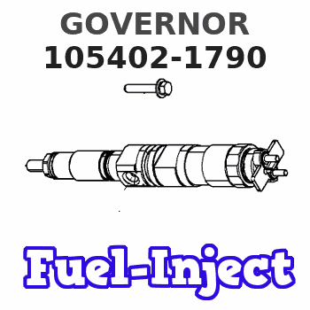
Information governor
BOSCH
9 420 610 179
9420610179
ZEXEL
105402-1790
1054021790
Rating:
Scheme ###:
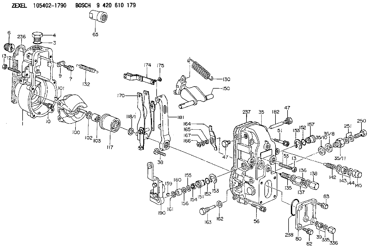
| 1. | [1] | 154000-6300 | GOVERNOR HOUSING |
| 3. | [1] | 029632-5070 | O-RING |
| 4. | [1] | 154007-2900 | CAPSULE |
| 6. | [1] | 154007-0200 | ADAPTOR |
| 7. | [1] | 020018-1840 | BLEEDER SCREW M8P1.25L18 |
| 9. | [1] | 154350-1800 | PLATE |
| 10. | [5] | 029010-6810 | BLEEDER SCREW |
| 11. | [1] | 020106-1640 | BLEEDER SCREW M6P1.0L14 |
| 12. | [1] | 154010-0100 | FLAT-HEAD SCREW |
| 13. | [2] | 154011-0100 | HEXAGON NUT |
| 13. | [2] | 154011-0100 | HEXAGON NUT |
| 35. | [1] | 154500-0520 | GOVERNOR COVER |
| 35/8. | [1] | 014110-3440 | LOCKING WASHER |
| 35/10. | [1] | 026516-2040 | GASKET D19.9&16.2T1 |
| 35/11. | [1] | 154316-4500 | ADAPTOR |
| 38. | [1] | 154031-2200 | FLAT-HEAD SCREW |
| 39. | [1] | 139206-0600 | UNION NUT |
| 47. | [2] | 154036-0300 | CAPSULE |
| 47. | [2] | 154036-0300 | CAPSULE |
| 51. | [2] | 020106-5040 | BLEEDER SCREW |
| 53. | [1] | 154010-0300 | FLAT-HEAD SCREW |
| 56. | [4] | 020106-3840 | BLEEDER SCREW |
| 65. | [1] | 154050-1720 | STOPPING DEVICE |
| 80. | [1] | 154060-8800 | COVER |
| 82. | [2] | 020506-1440 | BLEEDER SCREW |
| 83. | [2] | 020006-1440 | BLEEDER SCREW M6P1L14 |
| 85. | [2] | 014110-6440 | LOCKING WASHER |
| 100. | [1] | 154100-4820 | FLYWEIGHT ASSEMBLY |
| 101. | [1] | 025803-1610 | WOODRUFF KEY |
| 102. | [1] | 029321-2020 | LOCKING WASHER |
| 103. | [1] | 029231-2030 | UNION NUT |
| 117. | [1] | 154123-0120 | SLIDING PIECE |
| 118/1. | [0] | 029311-0010 | SHIM D14&10.1T0.2 |
| 118/1. | [0] | 029311-0180 | SHIM D14&10.1T0.3 |
| 118/1. | [0] | 029311-0190 | SHIM D14&10.1T0.40 |
| 118/1. | [0] | 029311-0210 | SHIM D14&10.1T1 |
| 118/1. | [0] | 139410-0000 | SHIM D14.0&10.1T0.5 |
| 118/1. | [0] | 139410-0100 | SHIM D14.0&10.1T1.5 |
| 118/1. | [0] | 139410-3000 | SHIM D14&10.1T2.0 |
| 118/1. | [0] | 139410-3100 | SHIM D14&10.1T3.0 |
| 118/1. | [0] | 139410-3200 | SHIM D14&10.1T4.0 |
| 130. | [1] | 154150-0200 | GOVERNOR SPRING |
| 132. | [1] | 154154-1200 | COILED SPRING |
| 135. | [1] | 154157-2320 | HEADLESS SCREW |
| 136. | [1] | 029201-2130 | UNION NUT M12P1.0H6 |
| 137. | [2] | 026512-1540 | GASKET D15.4&12.2T1.50 |
| 138. | [1] | 154159-1200 | CAP NUT |
| 140. | [1] | 154175-0920 | HEADLESS SCREW |
| 141. | [1] | 029201-6010 | UNION NUT |
| 142. | [1] | 154242-1020 | HEADLESS SCREW |
| 143. | [1] | 029201-6150 | UNION NUT |
| 144. | [2] | 026516-2040 | GASKET D19.9&16.2T1 |
| 145. | [1] | 154159-1100 | CAP NUT |
| 150. | [1] | 154200-7020 | SWIVELLING LEVER |
| 151. | [1] | 154204-3000 | BUSHING |
| 152. | [2] | 029631-8020 | O-RING |
| 152. | [2] | 029631-8020 | O-RING |
| 153. | [2] | 016010-1640 | LOCKING WASHER |
| 153. | [2] | 016010-1640 | LOCKING WASHER |
| 154. | [1] | 139611-0000 | PACKING RING |
| 155. | [1] | 139411-0000 | SHIM |
| 156. | [0] | 029311-1070 | SHIM D16&11T0.5 |
| 157. | [1] | 154204-3100 | BUSHING |
| 159. | [1] | 025803-1310 | WOODRUFF KEY |
| 160. | [1] | 154206-2800 | BUSHING |
| 161. | [0] | 154206-0200 | PLAIN WASHER D19.5&11.2T1.0 |
| 162. | [1] | 029331-0240 | GASKET |
| 163. | [1] | 154401-2700 | BLEEDER SCREW |
| 164. | [1] | 154243-0220 | CONTROL LEVER |
| 165. | [1] | 154327-1900 | COILED SPRING |
| 166. | [1] | 016010-0740 | LOCKING WASHER |
| 167. | [1] | 029310-8020 | PLAIN WASHER D15&8.4T0.3 |
| 170. | [1] | 154211-4320 | FORK LEVER |
| 174. | [1] | 154230-3920 | STRAP |
| 175. | [1] | 016010-0540 | LOCKING WASHER |
| 181. | [1] | 154236-3220 | TENSIONING LEVER |
| 182. | [1] | 154237-0100 | BEARING PIN |
| 190. | [1] | 154341-3320 | CONTROL LEVER |
| 236. | [1] | 154390-0000 | GASKET |
| 237. | [1] | 154390-0300 | GASKET |
| 238. | [1] | 029635-5010 | O-RING |
| 250. | [1] | 029731-2040 | EYE BOLT |
| 251. | [2] | 029341-2140 | GASKET |
| 335. | [2] | 026506-1040 | GASKET D9.9&6.2T1 |
| 336. | [1] | 154035-1600 | CAP NUT |
Include in #1:
101402-3300
as GOVERNOR
Cross reference number
Zexel num
Bosch num
Firm num
Name
105402-1790
9 420 610 179
GOVERNOR
* K
* K
Information:
The disconnect switch, if so equipped, must be in the ON position to let the electrical system function. There will be damage to some of the charging circuit components if the engine is running with the disconnect switch in the OFF position.
If the machine has a disconnect switch, the starting circuit can operate only after the disconnect switch is put in the ON position.The starting circuit is in operation only when the start switch is activated.The charging circuit is connected through the ammeter. The starting circuit is not connected through the ammeter.Charging System Components
The alternator is driven by V-type belts from the crankshaft pulley. The alternator is a three phase, self-rectifying charging unit, and the regulator is part of the alternator.Alternator
Alternator Components (Typical Example)
(1) Brush holder. (2) Rear frame. (3) Rotor. (4) Stator. (5) Drive end frame. (6) Fan assembly. (7) Slip rings. (8) Rectifier.The alternator used on the 3114 & 3116 Diesel Engines has three phase, full-wave, rectified output. It is a brush type alternator.The alternator is an electrical and mechanical component driven by a belt from engine rotation. It is used to charge the storage battery during engine operation. The alternator is cooled by a fan that is a part of the alternator. The fan pulls air through holes in the back of the alternator. The air exits the front of the alternator, cooling it in the process.The alternator converts mechanical and magnetic energy to alternating current (AC) and voltage. This process is done by rotating a direct current (DC) electromagnetic field (rotor) inside a three phase stator. The alternating current and voltage (generated by the stator) are changed to direct current by a three phase, full wave rectifier system using six silicone rectifier diodes. The alternator also has a diode trio which is an assembly made up of three exciter diodes. The diode trio rectifies field current needed to start the charging process. Direct current flows to the alternator output terminal.A solid state regulator is installed in the back of the alternator. Two brushes conduct current, through two slip rings, to the field coil on the rotor.There is also a capacitor mounted in the back of the alternator. The capacitor protects the rectifier from high voltages. It also suppresses radio noise.Regulator
The voltage regulator is a solid state (transistor, stationary parts) electronic switch which controls the alternator output. The regulator limits the alternator voltage to a preset value by controlling the field current. It feels the voltage in the system and switches "ON" and "OFF" many times a second to control the field current (DC current to the field windings) for the alternator to make the needed voltage output. Refer to Service Manual, Form No. SENR3862, for detailed service information for the alternator. For engines which have the alternator connected to an engine component, the ground strap must connect that component to the frame or to the battery ground.Starting System Components
Solenoid
A solenoid is an electromagnetic switch that does two basic operations:a. Closes the high current starter