Information governor
BOSCH
9 420 610 330
9420610330
ZEXEL
105402-1440
1054021440
Rating:
Scheme ###:
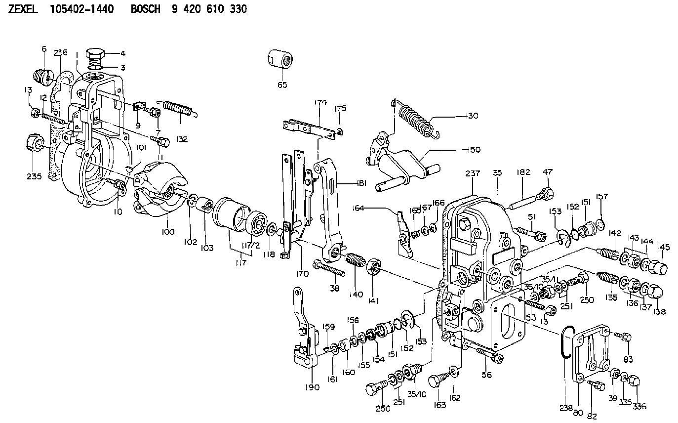
| 1. | [1] | 154000-6300 | GOVERNOR HOUSING |
| 3. | [1] | 029632-5070 | O-RING |
| 4. | [1] | 154007-2900 | CAPSULE |
| 6. | [1] | 154007-0200 | ADAPTOR |
| 7. | [1] | 020018-1840 | BLEEDER SCREW M8P1.25L18 |
| 9. | [1] | 154350-1900 | PLATE |
| 10. | [6] | 029010-6810 | BLEEDER SCREW |
| 12. | [1] | 154010-0100 | FLAT-HEAD SCREW |
| 13. | [2] | 154011-0100 | HEXAGON NUT |
| 13. | [2] | 154011-0100 | HEXAGON NUT |
| 35. | [1] | 154500-0820 | GOVERNOR COVER |
| 35/8. | [1] | 014110-3440 | LOCKING WASHER |
| 35/10. | [1] | 131002-3900 | ADAPTOR |
| 35/10. | [1] | 131002-3900 | ADAPTOR |
| 38. | [1] | 154031-2200 | FLAT-HEAD SCREW |
| 39. | [1] | 139206-0600 | UNION NUT |
| 47. | [2] | 154036-0300 | CAPSULE |
| 51. | [2] | 020106-5040 | BLEEDER SCREW |
| 53. | [1] | 154010-0300 | FLAT-HEAD SCREW |
| 56. | [4] | 020106-3840 | BLEEDER SCREW |
| 65. | [1] | 155404-3700 | CAP |
| 80. | [1] | 154060-8800 | COVER |
| 82. | [2] | 020506-1440 | BLEEDER SCREW |
| 83. | [2] | 020006-1440 | BLEEDER SCREW M6P1L14 |
| 85. | [2] | 014110-6440 | LOCKING WASHER |
| 100. | [1] | 154100-9720 | FLYWEIGHT ASSEMBLY |
| 101. | [1] | 025803-1610 | WOODRUFF KEY |
| 102. | [1] | 029321-2020 | LOCKING WASHER |
| 103. | [1] | 029231-2030 | UNION NUT |
| 117. | [1] | 154123-0120 | SLIDING PIECE |
| 118/1. | [0] | 029311-0010 | SHIM D14&10.1T0.2 |
| 118/1. | [0] | 029311-0180 | SHIM D14&10.1T0.3 |
| 118/1. | [0] | 029311-0190 | SHIM D14&10.1T0.40 |
| 118/1. | [0] | 029311-0210 | SHIM D14&10.1T1 |
| 118/1. | [0] | 139410-0000 | SHIM D14.0&10.1T0.5 |
| 118/1. | [0] | 139410-0100 | SHIM D14.0&10.1T1.5 |
| 118/1. | [0] | 139410-3000 | SHIM D14&10.1T2.0 |
| 118/1. | [0] | 139410-3100 | SHIM D14&10.1T3.0 |
| 118/1. | [0] | 139410-3200 | SHIM D14&10.1T4.0 |
| 130. | [1] | 154150-0100 | GOVERNOR SPRING |
| 132. | [1] | 154154-0800 | COILED SPRING |
| 135. | [1] | 154157-0120 | HEADLESS SCREW |
| 136. | [1] | 029201-2130 | UNION NUT M12P1.0H6 |
| 137. | [2] | 026512-1540 | GASKET D15.4&12.2T1.50 |
| 138. | [1] | 154159-1200 | CAP NUT |
| 140. | [1] | 154175-0420 | HEADLESS SCREW |
| 141. | [1] | 029201-6010 | UNION NUT |
| 142. | [1] | 154242-0320 | HEADLESS SCREW |
| 143. | [1] | 029201-6150 | UNION NUT |
| 144. | [2] | 026516-2040 | GASKET D19.9&16.2T1 |
| 145. | [1] | 154159-1100 | CAP NUT |
| 150. | [1] | 154200-7020 | SWIVELLING LEVER |
| 151. | [1] | 154204-3000 | BUSHING |
| 151. | [1] | 154204-3000 | BUSHING |
| 152. | [2] | 029631-8020 | O-RING |
| 152. | [2] | 029631-8020 | O-RING |
| 153. | [2] | 016010-1640 | LOCKING WASHER |
| 153. | [2] | 016010-1640 | LOCKING WASHER |
| 154. | [1] | 139611-0000 | PACKING RING |
| 155. | [1] | 139411-0000 | SHIM |
| 156. | [0] | 029311-1070 | SHIM D16&11T0.5 |
| 157. | [1] | 154204-3100 | BUSHING |
| 159. | [1] | 025803-1310 | WOODRUFF KEY |
| 160. | [1] | 154206-2800 | BUSHING |
| 161. | [0] | 154206-0200 | PLAIN WASHER D19.5&11.2T1.0 |
| 162. | [1] | 029331-0240 | GASKET |
| 163. | [1] | 154401-2700 | BLEEDER SCREW |
| 164. | [1] | 154243-0320 | CONTROL LEVER |
| 165. | [1] | 154327-2000 | COILED SPRING |
| 166. | [1] | 016010-0740 | LOCKING WASHER |
| 167. | [1] | 029310-8020 | PLAIN WASHER D15&8.4T0.3 |
| 170. | [1] | 154210-9020 | FORK LEVER |
| 174. | [1] | 154230-3920 | STRAP |
| 175. | [1] | 016010-0540 | LOCKING WASHER |
| 181. | [1] | 154236-3320 | TENSIONING LEVER |
| 182. | [1] | 154237-0100 | BEARING PIN |
| 190. | [1] | 154345-2320 | CONTROL LEVER |
| 202. | [1] | 131002-3900 | ADAPTOR |
| 236. | [1] | 154390-0000 | GASKET |
| 237. | [1] | 154390-0300 | GASKET |
| 238. | [1] | 029636-5010 | O-RING |
| 250. | [1] | 029731-2040 | EYE BOLT |
| 250. | [1] | 029731-2040 | EYE BOLT |
| 251. | [2] | 029341-2140 | GASKET |
| 251. | [2] | 029341-2140 | GASKET |
| 335. | [2] | 026506-1040 | GASKET D9.9&6.2T1 |
| 336. | [1] | 154035-1600 | CAP NUT |
Include in #1:
101492-3320
as GOVERNOR
Cross reference number
Zexel num
Bosch num
Firm num
Name
105402-1440
GOVERNOR
K 14JB MECHANICAL GOVERNOR GOV RSV GOV
K 14JB MECHANICAL GOVERNOR GOV RSV GOV
Information:
At operating temperature, the engine cooling system is hot and under pressure. Steam can cause personal injury. Check the coolant level only after the engine has been stopped and the fill cap on the radiator is cool enough to touch with your bare hand. Remove the fill cap slowly to relieve pressure. Cooling system conditioner contains alkali. Avoid contact with skin and eyes to prevent personal injury.
1. Drain the coolant from the cooling system into a suitable container for disposal.2. Remove the top radiator hose. 3. Remove four bolts (1) and the washers. Remove regulator housing (2) and the water temperature regulator as a unit. 4. Remove regulator housing gasket (4) from the regulator housing. Remove water temperature regulator (3).5. Remove the lip-type seal from the regulator housing. The following steps are for the installation of the water temperature regulator.6. Install the lip-type seal in the regulator housing with tool (A). Install the lip facing in toward the inside of the housing and until it makes contact with the counterbore in the housing. Lubricate the lip seal with glycerin.7. Install water temperature regulator (3) in the regulator housing.8. Put gasket (4) and regulator housing (2) in position, and install the four washers and bolts (1) that hold it.9. Connect the top radiator hose to the regulator housing.10. Fill the cooling system with coolant to the correct level. See the Operation & Maintenance Manual for the correct filling procedure.