Information governor
BOSCH
F 019 Z2E 672
f019z2e672
ZEXEL
105401-0931
1054010931
NISSAN-DIESEL
1910195Z02
1910195z02

Rating:
Scheme ###:
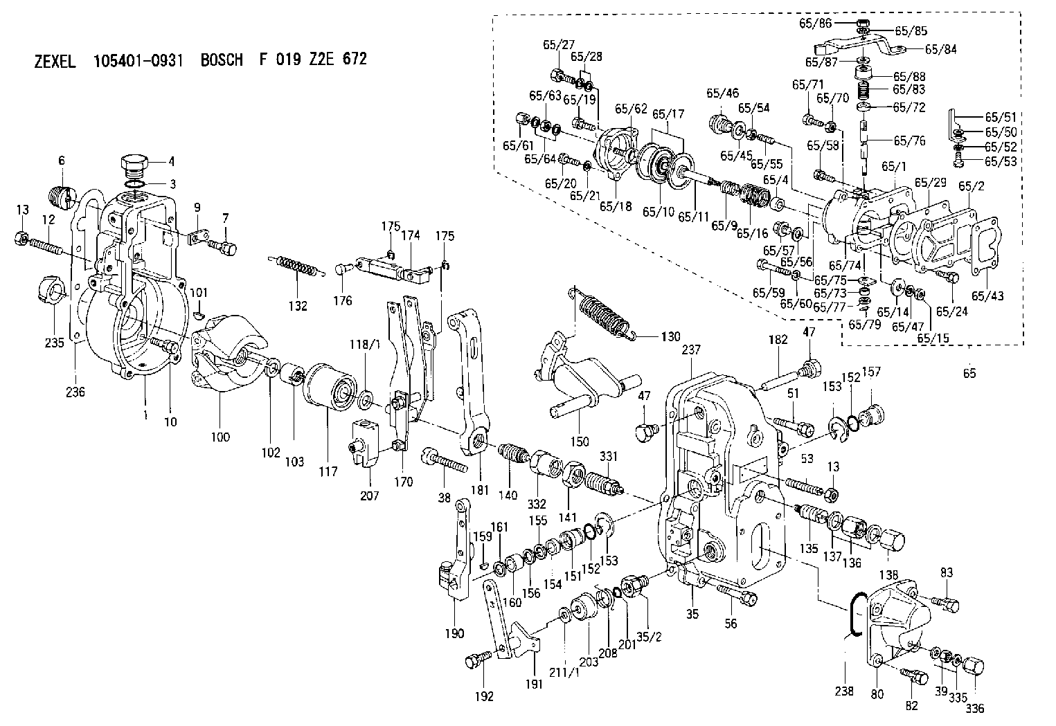
| 1. | [1] | 154000-6300 | GOVERNOR HOUSING |
| 3. | [1] | 029632-5070 | O-RING |
| 4. | [1] | 154007-2900 | CAPSULE |
| 6. | [1] | 154007-0200 | ADAPTOR |
| 7. | [1] | 020018-1840 | BLEEDER SCREW M8P1.25L18 |
| 9. | [1] | 154350-1900 | PLATE |
| 10. | [6] | 029010-6810 | BLEEDER SCREW |
| 12. | [1] | 154010-0100 | FLAT-HEAD SCREW |
| 13. | [2] | 154011-0100 | HEXAGON NUT |
| 13. | [2] | 154011-0100 | HEXAGON NUT |
| 35. | [1] | 154500-1020 | GOVERNOR COVER |
| 35/2. | [1] | 154321-0400 | BUSHING |
| 38. | [1] | 154031-3000 | FLAT-HEAD SCREW |
| 39. | [1] | 139206-0600 | UNION NUT |
| 47. | [2] | 154036-0300 | CAPSULE |
| 47. | [2] | 154036-0300 | CAPSULE |
| 51. | [2] | 020106-5040 | BLEEDER SCREW |
| 53. | [1] | 154010-0200 | FLAT-HEAD SCREW |
| 56. | [4] | 020106-3840 | BLEEDER SCREW |
| 65. | [1] | 154422-9820 | MANIFOLD-PRESSURE COMP. |
| 65/1. | [1] | 154415-3720 | DIAPHRAGM HOUSING |
| 65/2. | [1] | 154412-0401 | SPACER BUSHING |
| 65/4. | [1] | 154413-0500 | BUSHING |
| 65/9. | [1] | 154402-1900 | COILED SPRING |
| 65/10. | [1] | 154400-8220 | DIAPHRAGM |
| 65/11. | [1] | 154400-8400 | STOP PIN |
| 65/14. | [1] | 154406-5500 | SLOTTED WASHER |
| 65/15. | [1] | 013020-6040 | UNION NUT M6P1H5 |
| 65/16. | [1] | 154402-3200 | COILED SPRING |
| 65/17. | [2] | 154413-2600 | GASKET |
| 65/18. | [1] | 154404-5000 | COVER |
| 65/19. | [1] | 020106-2040 | BLEEDER SCREW M6P1L20 |
| 65/20. | [2] | 139006-7000 | BLEEDER SCREW |
| 65/21. | [2] | 014110-6440 | LOCKING WASHER |
| 65/24. | [2] | 020106-1640 | BLEEDER SCREW M6P1.0L14 |
| 65/27. | [1] | 029731-0180 | EYE BOLT |
| 65/28. | [2] | 026510-1340 | GASKET D13.4&10.2T1 |
| 65/29. | [1] | 154390-3700 | GASKET |
| 65/43. | [1] | 154390-3400 | GASKET |
| 65/45. | [1] | 029331-8040 | GASKET |
| 65/46. | [1] | 154406-5800 | FLAT-HEAD SCREW |
| 65/47. | [1] | 014110-6440 | LOCKING WASHER |
| 65/50. | [1] | 154406-6200 | SPACER BUSHING |
| 65/51. | [1] | 154406-8900 | PLATE |
| 65/52. | [1] | 014110-6440 | LOCKING WASHER |
| 65/53. | [1] | 154406-6400 | BLEEDER SCREW |
| 65/54. | [1] | 013020-6040 | UNION NUT M6P1H5 |
| 65/55. | [1] | 154404-1200 | FLAT-HEAD SCREW |
| 65/56. | [1] | 029331-2130 | GASKET |
| 65/57. | [1] | 154406-6500 | FLAT-HEAD SCREW |
| 65/58. | [1] | 020106-2240 | BLEEDER SCREW |
| 65/59. | [2] | 010006-7040 | BLEEDER SCREW M6P1L70 |
| 65/60. | [2] | 014110-6440 | LOCKING WASHER |
| 65/61. | [1] | 154035-1600 | CAP NUT |
| 65/62. | [1] | 154404-4400 | FLAT-HEAD SCREW |
| 65/63. | [1] | 023040-6040 | UNION NUT |
| 65/64. | [2] | 026506-1040 | GASKET D9.9&6.2T1 |
| 65/70. | [1] | 029240-6010 | UNION NUT M6P1.0H5* |
| 65/71. | [1] | 153141-1600 | BLEEDER SCREW |
| 65/72. | [1] | 139608-0500 | PACKING RING |
| 65/73. | [1] | 139605-0000 | PACKING RING |
| 65/74. | [1] | 154412-6900 | CONTROL LEVER |
| 65/75. | [1] | 154406-7500 | CONTROL LEVER |
| 65/76. | [1] | 154412-7000 | LEVER SHAFT |
| 65/77. | [1] | 029310-5200 | SHIM |
| 65/79. | [1] | 154372-6500 | SAFETY PIN |
| 65/83. | [1] | 154415-3900 | COILED SPRING |
| 65/84. | [1] | 154412-7100 | CONTROL LEVER |
| 65/85. | [1] | 014110-8440 | LOCKING WASHER |
| 65/86. | [1] | 013020-8140 | UNION NUT M8P1.25H6.5 |
| 65/87. | [0] | 154415-4000 | PLAIN WASHER |
| 65/88. | [1] | 154415-4100 | CAP |
| 80. | [1] | 154063-5100 | COVER |
| 82. | [2] | 029020-6210 | BLEEDER SCREW |
| 83. | [2] | 020006-1640 | BLEEDER SCREW M6P1L16 4T |
| 100. | [1] | 154100-9720 | FLYWEIGHT ASSEMBLY |
| 101. | [1] | 025803-1610 | WOODRUFF KEY |
| 102. | [1] | 029321-2020 | LOCKING WASHER |
| 103. | [1] | 029231-2030 | UNION NUT |
| 117. | [1] | 154123-2320 | SLIDING PIECE |
| 118/1. | [0] | 029311-0010 | SHIM D14&10.1T0.2 |
| 118/1. | [0] | 029311-0180 | SHIM D14&10.1T0.3 |
| 118/1. | [0] | 029311-0190 | SHIM D14&10.1T0.40 |
| 118/1. | [0] | 029311-0210 | SHIM D14&10.1T1 |
| 118/1. | [0] | 139410-0000 | SHIM D14.0&10.1T0.5 |
| 118/1. | [0] | 139410-0100 | SHIM D14.0&10.1T1.5 |
| 118/1. | [0] | 139410-3000 | SHIM D14&10.1T2.0 |
| 118/1. | [0] | 139410-3100 | SHIM D14&10.1T3.0 |
| 118/1. | [0] | 139410-3200 | SHIM D14&10.1T4.0 |
| 130. | [1] | 154150-2900 | GOVERNOR SPRING |
| 132. | [1] | 154154-0500 | COILED SPRING |
| 135. | [1] | 154158-0820 | HEADLESS SCREW |
| 136. | [1] | 154011-1700 | UNION NUT |
| 137. | [2] | 026512-1540 | GASKET D15.4&12.2T1.50 |
| 138. | [1] | 154159-1200 | CAP NUT |
| 140. | [1] | 154185-1320 | HEADLESS SCREW |
| 141. | [1] | 029201-6080 | UNION NUT |
| 150. | [1] | 154200-7020 | SWIVELLING LEVER |
| 151. | [1] | 154204-4300 | BUSHING |
| 152. | [2] | 029631-8020 | O-RING |
| 152. | [2] | 029631-8020 | O-RING |
| 153. | [2] | 016010-1640 | LOCKING WASHER |
| 153. | [2] | 016010-1640 | LOCKING WASHER |
| 154. | [1] | 139611-0000 | PACKING RING |
| 155. | [1] | 139411-0000 | SHIM |
| 156. | [0] | 029311-1070 | SHIM D16&11T0.5 |
| 157. | [1] | 154204-4400 | BUSHING |
| 159. | [1] | 025803-1310 | WOODRUFF KEY |
| 160. | [1] | 154206-2800 | BUSHING |
| 161. | [0] | 154206-0200 | PLAIN WASHER D19.5&11.2T1.0 |
| 170. | [1] | 154210-0920 | FORK LEVER |
| 174. | [1] | 154230-4320 | STRAP |
| 175. | [2] | 016010-0540 | LOCKING WASHER |
| 175. | [2] | 016010-0540 | LOCKING WASHER |
| 176. | [1] | 154222-4300 | BEARING PIN |
| 181. | [1] | 154236-4100 | TENSIONING LEVER |
| 182. | [1] | 154237-0100 | BEARING PIN |
| 190. | [1] | 154309-6120 | CONTROL LEVER |
| 191. | [1] | 154365-9321 | CONTROL LEVER |
| 192. | [1] | 020006-4540 | BLEEDER SCREW M6P1L45 |
| 201. | [1] | 029631-0030 | O-RING &9.8W2.3 |
| 203. | [1] | 154322-0100 | CAP |
| 207. | [1] | 154326-5020 | CONTROL LEVER |
| 208. | [1] | 154327-7600 | COILED SPRING |
| 211/1. | [0] | 029311-0520 | SHIM D20.8&10.3T0.2 |
| 211/1. | [0] | 029311-0530 | SHIM D20.8&10.3T0.25 |
| 211/1. | [0] | 029311-0540 | SHIM D20.8&10.3T0.3 |
| 211/1. | [0] | 029311-0550 | SHIM D20.8&10.3T0.35 |
| 211/1. | [0] | 029311-0560 | SHIM D20.8&10.3T0.4 |
| 211/1. | [0] | 029311-0570 | SHIM D20.8&10.3T0.5 |
| 235. | [1] | 155412-5200 | IMPELLER WHEEL |
| 236. | [1] | 154390-0000 | GASKET |
| 237. | [1] | 154390-0300 | GASKET |
| 238. | [1] | 029635-2020 | O-RING |
| 331. | [1] | 154179-5520 | HEADLESS SCREW |
| 332. | [1] | 029201-6010 | UNION NUT |
| 335. | [2] | 026506-1040 | GASKET D9.9&6.2T1 |
| 336. | [1] | 154035-1600 | CAP NUT |
Include in #1:
101605-9491
as GOVERNOR
Cross reference number
Zexel num
Bosch num
Firm num
Name
105401-0931
1910195Z02 NISSAN-DIESEL
GOVERNOR
K 14JB MECHANICAL GOVERNOR GOV RSV GOV
K 14JB MECHANICAL GOVERNOR GOV RSV GOV
Information:
1. Drain the coolant from the radiator. 2. Remove bolts (1) and grill (2). 3. Remove bolts (5) and fan guard (3). Remove bolts (6) and support bracket (4). Remove the enclosure group top panel (7).4. Remove the bolts holding the enclosure group side panels. Remove the side panels.5. Loosen the hose clamps on the upper and lower radiator hoses. Disconnect the radiator hoses from the radiator. 6. Use tooling (A) and attach a hoist to radiator (8). Remove the lower bolts holding the radiator to the base. Remove radiator (8). The weight of the radiator is 73 kg (161 lb.). The following steps are for the installation of the radiator.7. Use a hoist to install the radiator on the base. Install the bolts. Remove the hoist and tooling (A) from the radiator.8. Connect the upper and lower radiator hoses to the radiator. Tighten the hose clamps.9. Install the enclosure group side panels.10. Install the enclosure group top panel. Install the grill and the fan guard.11. Fill the radiator with coolant to the correct level. See the Maintenance Manual.Remove And Install Radiator And Radiator Guard (Prime)
1. Drain the coolant from the radiator. 2. Loosen hose clamps (4) and (5). Disconnect tube (1) from hose (6). Rotate tube (1) 180° for clearance. Remove bolts (2) from support arms (3). 3. Remove eight bolts (7) holding fan guard (8) to the radiator guard. 4. Install tool (A) and a hoist to the radiator. 5. Remove four bolts (10) that fasten the lower radiator elbow to the radiator. Separate the elbow from the radiator. Remove bolt (11) from the crankcase vent hose clamp.Remove four mounting bolts (9). Remove the radiator and radiator guard. The weight of the radiator and radiator guard is 250 Kg (550 lb.). The following steps are for the installation of the radiator and radiator guard.6. Use a hoist to put the radiator and radiator guard in position on the base. Install four mounting bolts (9). Remove the hoist and tool (A).7. Install the gasket and lower radiator elbow (12) to the radiator. Install bolts (10). Install bolt (11) and the clamp to hold the crankcase vent hose in place.8. Install bolts (7) to hold fan guard (8) in position.9. Connect tube (1) to hose (6) and tighten hose clamps (4) and (5). Install bolts (2) to secure control arms (3) to the radiator guard.10. Fill the radiator with coolant to the correct level. See the Maintenance Manual.Disassemble And Assemble Radiator
Start By:a. remove radiator and radiator guard **The radiator can be disassembled and assembled without removing the radiator and guard. 1. Remove eighteen bolts (2) and remove four plates (4). Remove four bolts, block off plate (1) and the gasket. Remove four bolts, upper radiator hose adapter (3) and the gasket. 2. Loosen four bolts (7). Disconnect tube assemblies (5) and (8). Remove four bolts (9) and remove coolant level switch if applicable. 3. Remove eleven bolts (11) and remove overflow tube (10), crankcase vent tube clamp (13)