Information governor
BOSCH
9 420 611 479
9420611479
ZEXEL
105401-0900
1054010900
Rating:
Scheme ###:
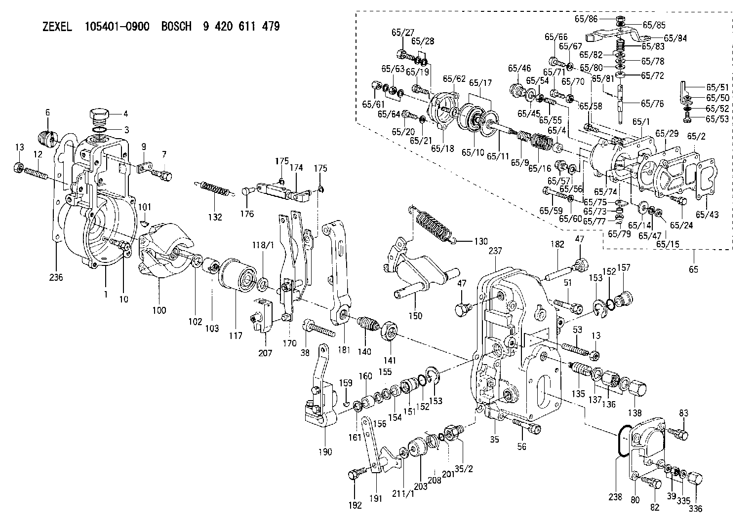
| 1. | [1] | 154000-6300 | GOVERNOR HOUSING |
| 3. | [1] | 029632-5070 | O-RING |
| 4. | [1] | 154007-2900 | CAPSULE |
| 6. | [1] | 154007-0200 | ADAPTOR |
| 7. | [1] | 020018-1840 | BLEEDER SCREW M8P1.25L18 |
| 9. | [1] | 154350-1900 | PLATE |
| 10. | [6] | 029010-6810 | BLEEDER SCREW |
| 12. | [1] | 154010-0100 | FLAT-HEAD SCREW |
| 13. | [2] | 154011-0100 | HEXAGON NUT |
| 13. | [2] | 154011-0100 | HEXAGON NUT |
| 35. | [1] | 154500-1020 | GOVERNOR COVER |
| 35/2. | [1] | 154321-0400 | BUSHING |
| 38. | [1] | 154031-2400 | FLAT-HEAD SCREW |
| 39. | [1] | 139206-0600 | UNION NUT |
| 47. | [2] | 154036-0300 | CAPSULE |
| 47. | [2] | 154036-0300 | CAPSULE |
| 51. | [2] | 020106-5040 | BLEEDER SCREW |
| 53. | [1] | 154010-0200 | FLAT-HEAD SCREW |
| 56. | [4] | 020106-3840 | BLEEDER SCREW |
| 65. | [1] | 154421-6120 | MANIFOLD-PRESSURE COMP. |
| 65/1. | [1] | 154412-6821 | DIAPHRAGM HOUSING |
| 65/2. | [1] | 154412-0401 | SPACER BUSHING |
| 65/4. | [1] | 154413-0500 | BUSHING |
| 65/9. | [1] | 154403-8600 | COILED SPRING |
| 65/10. | [1] | 154400-8220 | DIAPHRAGM |
| 65/11. | [1] | 154400-8400 | STOP PIN |
| 65/14. | [1] | 154406-5500 | SLOTTED WASHER |
| 65/15. | [1] | 013020-6040 | UNION NUT M6P1H5 |
| 65/16. | [1] | 154403-9800 | COILED SPRING |
| 65/17. | [2] | 154413-2600 | GASKET |
| 65/18. | [1] | 154404-5000 | COVER |
| 65/19. | [1] | 020106-2040 | BLEEDER SCREW M6P1L20 |
| 65/20. | [2] | 139006-7000 | BLEEDER SCREW |
| 65/21. | [2] | 014110-6440 | LOCKING WASHER |
| 65/24. | [2] | 020106-1640 | BLEEDER SCREW M6P1.0L14 |
| 65/27. | [1] | 029731-0180 | EYE BOLT |
| 65/28. | [2] | 026510-1340 | GASKET D13.4&10.2T1 |
| 65/29. | [1] | 154390-3700 | GASKET |
| 65/43. | [1] | 154390-3400 | GASKET |
| 65/45. | [1] | 029331-8040 | GASKET |
| 65/46. | [1] | 154406-5800 | FLAT-HEAD SCREW |
| 65/47. | [1] | 014110-6440 | LOCKING WASHER |
| 65/50. | [1] | 154406-6200 | SPACER BUSHING |
| 65/51. | [1] | 154406-8900 | PLATE |
| 65/52. | [1] | 014110-6440 | LOCKING WASHER |
| 65/53. | [1] | 154406-6400 | BLEEDER SCREW |
| 65/54. | [1] | 013020-6040 | UNION NUT M6P1H5 |
| 65/55. | [1] | 154404-1200 | FLAT-HEAD SCREW |
| 65/56. | [1] | 029331-2130 | GASKET |
| 65/57. | [1] | 154406-6500 | FLAT-HEAD SCREW |
| 65/58. | [1] | 020106-2240 | BLEEDER SCREW |
| 65/59. | [2] | 010006-7040 | BLEEDER SCREW M6P1L70 |
| 65/60. | [2] | 014110-6440 | LOCKING WASHER |
| 65/61. | [1] | 154035-1600 | CAP NUT |
| 65/62. | [1] | 154404-4400 | FLAT-HEAD SCREW |
| 65/63. | [1] | 023040-6040 | UNION NUT |
| 65/64. | [2] | 026506-1040 | GASKET D9.9&6.2T1 |
| 65/66. | [1] | 139006-0900 | BLEEDER SCREW |
| 65/67. | [1] | 014110-6440 | LOCKING WASHER |
| 65/70. | [1] | 029240-6010 | UNION NUT M6P1.0H5* |
| 65/71. | [1] | 153141-1600 | BLEEDER SCREW |
| 65/72. | [1] | 139608-0000 | PACKING RING |
| 65/73. | [1] | 139605-0100 | PACKING RING |
| 65/74. | [1] | 154412-6900 | CONTROL LEVER |
| 65/75. | [1] | 154406-7500 | CONTROL LEVER |
| 65/76. | [1] | 154412-7000 | LEVER SHAFT |
| 65/77. | [1] | 029310-5200 | SHIM |
| 65/78. | [1] | 014020-8120 | PLAIN WASHER D16&8.5T1.2 |
| 65/79. | [1] | 154372-6500 | SAFETY PIN |
| 65/80. | [0] | 029310-8040 | SHIM D13.5&8T0.2 |
| 65/80B. | [0] | 029310-8050 | SHIM D13.5&8T0.5 |
| 65/81. | [1] | 025520-1210 | SPLIT PIN |
| 65/82. | [2] | 029300-8320 | SHIM |
| 65/83. | [1] | 154403-9900 | COILED SPRING |
| 65/84. | [1] | 154412-7100 | CONTROL LEVER |
| 65/85. | [1] | 014110-8440 | LOCKING WASHER |
| 65/86. | [1] | 013020-8140 | UNION NUT M8P1.25H6.5 |
| 80. | [1] | 154063-1400 | COVER |
| 82. | [2] | 029020-6210 | BLEEDER SCREW |
| 83. | [2] | 020006-1640 | BLEEDER SCREW M6P1L16 4T |
| 100. | [1] | 154101-0120 | FLYWEIGHT |
| 101. | [1] | 025803-1610 | WOODRUFF KEY |
| 102. | [1] | 029321-2020 | LOCKING WASHER |
| 103. | [1] | 029231-2030 | UNION NUT |
| 117. | [1] | 154123-2320 | SLIDING PIECE |
| 118/1. | [0] | 029311-0010 | SHIM D14&10.1T0.2 |
| 118/1. | [0] | 029311-0180 | SHIM D14&10.1T0.3 |
| 118/1. | [0] | 029311-0190 | SHIM D14&10.1T0.40 |
| 118/1. | [0] | 029311-0210 | SHIM D14&10.1T1 |
| 118/1. | [0] | 139410-0000 | SHIM D14.0&10.1T0.5 |
| 118/1. | [0] | 139410-0100 | SHIM D14.0&10.1T1.5 |
| 118/1. | [0] | 139410-3000 | SHIM D14&10.1T2.0 |
| 118/1. | [0] | 139410-3100 | SHIM D14&10.1T3.0 |
| 118/1. | [0] | 139410-3200 | SHIM D14&10.1T4.0 |
| 130. | [1] | 154150-0400 | GOVERNOR SPRING |
| 132. | [1] | 154154-0701 | COILED SPRING |
| 135. | [1] | 154158-1020 | HEADLESS SCREW |
| 136. | [1] | 154011-1700 | UNION NUT |
| 137. | [2] | 026512-1540 | GASKET D15.4&12.2T1.50 |
| 138. | [1] | 154159-1200 | CAP NUT |
| 140. | [1] | 154185-1320 | HEADLESS SCREW |
| 141. | [1] | 029201-6010 | UNION NUT |
| 150. | [1] | 154200-7020 | SWIVELLING LEVER |
| 151. | [1] | 154204-4300 | BUSHING |
| 152. | [2] | 029631-8020 | O-RING |
| 152. | [2] | 029631-8020 | O-RING |
| 153. | [2] | 016010-1640 | LOCKING WASHER |
| 153. | [2] | 016010-1640 | LOCKING WASHER |
| 154. | [1] | 139611-0000 | PACKING RING |
| 155. | [1] | 139411-0000 | SHIM |
| 156. | [0] | 029311-1070 | SHIM D16&11T0.5 |
| 157. | [1] | 154204-4400 | BUSHING |
| 159. | [1] | 025803-1310 | WOODRUFF KEY |
| 160. | [1] | 154206-2800 | BUSHING |
| 161. | [0] | 154206-0200 | PLAIN WASHER D19.5&11.2T1.0 |
| 170. | [1] | 154210-0920 | FORK LEVER |
| 174. | [1] | 154235-2220 | STRAP |
| 175. | [2] | 016010-0540 | LOCKING WASHER |
| 175. | [2] | 016010-0540 | LOCKING WASHER |
| 176. | [1] | 154222-4300 | BEARING PIN |
| 181. | [1] | 154236-4100 | TENSIONING LEVER |
| 182. | [1] | 154237-0100 | BEARING PIN |
| 190. | [1] | 154303-3120 | CONTROL LEVER |
| 191. | [1] | 154382-7420 | CONTROL LEVER |
| 192. | [1] | 020006-4040 | BLEEDER SCREW |
| 201. | [1] | 029631-0030 | O-RING &9.8W2.3 |
| 203. | [1] | 154322-0100 | CAP |
| 207. | [1] | 154326-5020 | CONTROL LEVER |
| 208. | [1] | 154327-7600 | COILED SPRING |
| 211/1. | [0] | 029311-0520 | SHIM D20.8&10.3T0.2 |
| 211/1. | [0] | 029311-0530 | SHIM D20.8&10.3T0.25 |
| 211/1. | [0] | 029311-0540 | SHIM D20.8&10.3T0.3 |
| 211/1. | [0] | 029311-0550 | SHIM D20.8&10.3T0.35 |
| 211/1. | [0] | 029311-0560 | SHIM D20.8&10.3T0.4 |
| 211/1. | [0] | 029311-0570 | SHIM D20.8&10.3T0.5 |
| 236. | [1] | 154390-0000 | GASKET |
| 237. | [1] | 154390-0300 | GASKET |
| 238. | [1] | 029635-2020 | O-RING |
| 335. | [2] | 026506-1040 | GASKET D9.9&6.2T1 |
| 336. | [1] | 154035-1600 | CAP NUT |
Include in #1:
101605-9460
as GOVERNOR
Cross reference number
Zexel num
Bosch num
Firm num
Name
Information:
Start By:a. remove cylinder headb. remove oil panc. remove underframe 1. Remove bolt and remove cooling jet (1).2. Check the connecting rods and caps for their identification and location. The connecting rod and the rod cap should have the cylinder number etched on the right side as indicated by the arrow.3. Remove rod cap bolts (2) and the cap from the connecting rod. Remove the lower half of the bearing from the cap. 4. Push piston and connecting rod (4) away from the crankshaft, then remove upper half of the rod bearing (5).5. Remove the piston and connecting rod. The following steps are for the installation of the pistons and connecting rod assemblies.6. Put clean oil on piston rings, piston and cylinder bore. 7. Position the piston ring end gaps 120° apart and install tooling (A).8. With number one crankshaft throw at bottom center, install piston and connecting rod. Some engines use pistons which have the word "FRONT" stamped on the crown of the piston. Make sure the word "FRONT" is toward the front of the engine when the piston is installed. The etched number on the connecting rod must be on the right side and must be installed in the corresponding cylinder.9. Taking care to line up connecting rod and crankshaft, carefully tap piston into cylinder bore until tooling (A) comes off the piston.10. Before connecting rod comes in contact with crankshaft, install upper half of rod bearing. Be sure the bearing tab properly engages the slot in the connecting rod.11. Put engine oil on upper rod bearing surface, then tap piston down, guiding connecting rod onto crankshaft.12. Position lower half of rod bearing in corresponding numbered rod cap. Be sure the bearing tab engages the grove in the rod caps.13. Put engine oil on the lower rod bearing surface, then install the rod cap. Install the bearing cap on the connecting rod with the number on the bearing (rod) cap on the same side and same number as on the connecting rod.14. Put 2P2506 Thread Lubricant on the threads of the bolts. Install rod cap bolts (1) and tighten them to a torque of 130 7 N m (95 5 lb.ft.). Mark each bolt head and then tighten each bolt an additional 60 5° (1/6 turn).15. Repeat the steps for the remainder of the pistons and connecting rods.End By:a. install underframeb. install oil panc. install cylinder headDisassemble And Assemble Pistons And Connecting Rods
Start By:a. remove pistons and connecting rods 1. Use tooling (A) and remove piston rings (1) from piston crown (2). 2. Remove snap ring and remove piston pin (3). Separate piston crown (2), piston skirt (4) and connecting rod (5). The connecting rod must be heated for the installation of the piston pin bearing. Do not use a torch.3. Heat connecting rod (5) in the area indicated by the illustration to a temperature of 175 to 260° C (347 to 500° F) to install the piston pin bearing. The bearing joint
Start By:a. remove pistons and connecting rods 1. Use tooling (A) and remove piston rings (1) from piston crown (2). 2. Remove snap ring and remove piston pin (3). Separate piston crown (2), piston skirt (4) and connecting rod (5). The connecting rod must be heated for the installation of the piston pin bearing. Do not use a torch.3. Heat connecting rod (5) in the area indicated by the illustration to a temperature of 175 to 260° C (347 to 500° F) to install the piston pin bearing. The bearing joint