Information governor
BOSCH
9 420 612 433
9420612433
ZEXEL
105401-0670
1054010670
Rating:
Scheme ###:
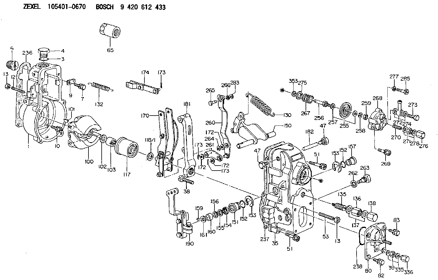
| 1. | [1] | 154000-6300 | GOVERNOR HOUSING |
| 3. | [1] | 029632-5070 | O-RING |
| 4. | [1] | 154007-2900 | CAPSULE |
| 6. | [1] | 154007-0200 | ADAPTOR |
| 7. | [1] | 020018-1840 | BLEEDER SCREW M8P1.25L18 |
| 9. | [1] | 154350-1900 | PLATE |
| 10. | [6] | 029010-6810 | BLEEDER SCREW |
| 12. | [1] | 154010-0100 | FLAT-HEAD SCREW |
| 13. | [2] | 154011-0100 | HEXAGON NUT |
| 13. | [2] | 154011-0100 | HEXAGON NUT |
| 35. | [1] | 154022-5320 | GOVERNOR COVER |
| 38. | [1] | 154031-1300 | FLAT-HEAD SCREW |
| 39. | [1] | 139206-0600 | UNION NUT |
| 47. | [2] | 154036-0300 | CAPSULE |
| 47. | [2] | 154036-0300 | CAPSULE |
| 51. | [6] | 020106-5040 | BLEEDER SCREW |
| 51. | [6] | 020106-5040 | BLEEDER SCREW |
| 53. | [1] | 154010-0300 | FLAT-HEAD SCREW |
| 65. | [1] | 154050-9020 | STOPPING DEVICE |
| 80. | [1] | 154063-6820 | COVER |
| 82. | [2] | 029020-6210 | BLEEDER SCREW |
| 83. | [2] | 020006-1640 | BLEEDER SCREW M6P1L16 4T |
| 100. | [1] | 154101-0120 | FLYWEIGHT |
| 101. | [1] | 025803-1610 | WOODRUFF KEY |
| 102. | [1] | 029321-2020 | LOCKING WASHER |
| 103. | [1] | 029231-2030 | UNION NUT |
| 117. | [1] | 154123-0120 | SLIDING PIECE |
| 118/1. | [0] | 029311-0010 | SHIM D14&10.1T0.2 |
| 118/1. | [0] | 029311-0180 | SHIM D14&10.1T0.3 |
| 118/1. | [0] | 029311-0190 | SHIM D14&10.1T0.40 |
| 118/1. | [0] | 029311-0210 | SHIM D14&10.1T1 |
| 118/1. | [0] | 139410-0000 | SHIM D14.0&10.1T0.5 |
| 118/1. | [0] | 139410-0100 | SHIM D14.0&10.1T1.5 |
| 118/1. | [0] | 139410-3000 | SHIM D14&10.1T2.0 |
| 118/1. | [0] | 139410-3100 | SHIM D14&10.1T3.0 |
| 118/1. | [0] | 139410-3200 | SHIM D14&10.1T4.0 |
| 130. | [1] | 154150-0400 | GOVERNOR SPRING |
| 132. | [1] | 154154-0701 | COILED SPRING |
| 135. | [1] | 154158-0920 | HEADLESS SCREW |
| 136. | [1] | 029201-2140 | UNION NUT |
| 137. | [2] | 026512-1540 | GASKET D15.4&12.2T1.50 |
| 138. | [1] | 154159-1200 | CAP NUT |
| 150. | [1] | 154200-7020 | SWIVELLING LEVER |
| 151. | [1] | 154204-3000 | BUSHING |
| 152. | [2] | 029631-8020 | O-RING |
| 152. | [2] | 029631-8020 | O-RING |
| 153. | [2] | 016010-1640 | LOCKING WASHER |
| 153. | [2] | 016010-1640 | LOCKING WASHER |
| 154. | [1] | 139611-0000 | PACKING RING |
| 155. | [1] | 139411-0000 | SHIM |
| 156. | [0] | 029311-1070 | SHIM D16&11T0.5 |
| 157. | [1] | 154204-3100 | BUSHING |
| 159. | [1] | 025803-1310 | WOODRUFF KEY |
| 160. | [1] | 154206-2800 | BUSHING |
| 161. | [0] | 154206-0200 | PLAIN WASHER D19.5&11.2T1.0 |
| 170. | [1] | 154211-4120 | FORK LEVER |
| 172. | [3] | 029310-5170 | SHIM D8&5.3T0.5 |
| 172. | [3] | 029310-5170 | SHIM D8&5.3T0.5 |
| 172. | [3] | 029310-5170 | SHIM D8&5.3T0.5 |
| 173. | [3] | 025520-1210 | SPLIT PIN |
| 173. | [3] | 025520-1210 | SPLIT PIN |
| 173. | [3] | 025520-1210 | SPLIT PIN |
| 174. | [1] | 154230-0120 | STRAP |
| 181. | [1] | 154236-4100 | TENSIONING LEVER |
| 182. | [1] | 154237-0100 | BEARING PIN |
| 190. | [1] | 154343-9220 | CONTROL LEVER |
| 236. | [1] | 154390-0000 | GASKET |
| 237. | [1] | 154390-0300 | GASKET |
| 238. | [1] | 029635-2020 | O-RING |
| 255. | [1] | 154400-7420 | DIAPHRAGM |
| 256. | [1] | 154400-4800 | STOP PIN |
| 257. | [2] | 029330-8050 | GASKET |
| 258. | [1] | 139308-0700 | LOCKING WASHER |
| 259. | [1] | 013030-6040 | UNION NUT M6P1H3.6 |
| 260. | [1] | 154401-0220 | CONTROL LEVER |
| 261. | [1] | 154401-1320 | STRAP |
| 262. | [1] | 026510-1440 | GASKET D13.9&10.2T1 |
| 263. | [1] | 154401-2100 | BLEEDER SCREW |
| 264. | [1] | 016010-0540 | LOCKING WASHER |
| 265. | [1] | 154222-6200 | BEARING PIN |
| 266. | [1] | 029300-4010 | PLAIN WASHER |
| 267. | [1] | 154411-5200 | COILED SPRING |
| 268. | [1] | 154404-5000 | COVER |
| 269. | [2] | 020106-2540 | BLEEDER SCREW M6P1L25 |
| 270. | [1] | 154404-1100 | FLAT-HEAD SCREW |
| 271. | [1] | 023040-6040 | UNION NUT |
| 272. | [1] | 029711-0140 | INLET UNION |
| 273. | [1] | 029731-0180 | EYE BOLT |
| 274. | [2] | 029341-0110 | GASKET |
| 275. | [0] | 029312-0180 | SHIM D25.5&20T0.5 |
| 275B. | [0] | 029312-0210 | SHIM D25.5&20T0.2 |
| 276. | [1] | 154035-0320 | CAP NUT |
| 277. | [1] | 014110-6440 | LOCKING WASHER |
| 278. | [2] | 154413-2600 | GASKET |
| 283. | [1] | 016010-0440 | LOCKING WASHER |
| 285. | [1] | 029010-6310 | BLEEDER SCREW |
| 335. | [2] | 026506-1040 | GASKET D9.9&6.2T1 |
| 336. | [1] | 154035-1600 | CAP NUT |
| 353. | [1] | 029310-9080 | SHIM D16&9T1.7 |
Include in #1:
101609-3130
as GOVERNOR
Cross reference number
Zexel num
Bosch num
Firm num
Name
Information:
1. Remove wiring harnesses from bracket (1). 2. Disconnect the wires at connections (5) Remove line (4). Remove five bolts (2), bracket (1) cover (3) and the gasket. 3. Remove two bolts (6) and clamps. Remove rack solenoid. (7) 4. Disconnect wires at connections (8). Remove two bolts (10) and bracket assembly (9). Loosen the locknut and remove rack position sensor (11). Be careful not to lose the spring that is around the sensor. To remove the transducer module at this time use the following procedure.a. disconnect wires at connector (8)b. remove the connector from the wiresc. remove four bolts that fasten transducer module (22) to housing (15)d. feed the wires through housing (18) while removing the transducer module. 5. Remove three bolts (12) from inside housing (14). Remove two bolts (13) and remove housing (14). 6. Loosen locknut (15) and remove engine speed sensor (16). 7. Remove seven bolts (17) and remove the transducer module and housing (18). 8. Remove three bolts (19) and cover (20). 9. Remove two bolts (21). Remove transducer module (22) and gasket. 10. Remove lockring (27), seat (25), spring (24), sleeve (23) and lockring (26). 11. Remove three bolts (28) and remove cylinder (29). 12. Remove sleeve (30), piston (31) and valve (32). Remove O-ring seal (33) from sleeve (30). 13. Remove bolts (34) and remove retainer (35). Remove two races and one bearing (not shown).Assemble Rack Actuator Package
1. Lubricate bearing (37) with engine oil. Install race (36), bearing (37), race (36) and retainer (35) on the fuel injection pump camshaft. 2. Lubricate O-ring seal (33) with engine oil and install on sleeve (30). Install sleeve (32) and piston (31) into sleeve (33). 3. Install sleeve (30) into cylinder (29).4. Install lockring (26), sleeve (23), spring (24), seat (25) and lockring (27) on valve (32). 5. Put cylinder assembly (29) in position on the fuel injection pump housing with piston (31) engaged over fuel injection pump rack (38). Be sure that rack (38) is properly engaged with piston (31). 6. Fasten cylinder (29) to the fuel injection pump housing with three bolts (28). The rack and servo valve (32) must move freely after bolts (28) are tight. 7. Install gasket (39) and transducer module (22) on housing (18). 8. Place wire harness (40) in the slot of the housing. 9. Install cover (20) and bolts (19). 10. Install the gasket and housing (18) on the fuel injection pump housing with seven bolts (17). 11. Install engine speed sensor (16) until it contacts retainer (35). Back the engine speed sensor out (counterclockwise) 180°. This procedure will provide a clearance of .76 mm (.030 in). Tighten locknut (15) to a torque of 13 2 N m (10 1 lb.ft.). 12. Install gasket and housing (14).13. Install the rack position sensor damping seal in housing (14). Install the spring and rack position sensor (11) in housing (14). 14. Connect the rack position sensor wiring connector to the transducer module wiring connector (P8 to
1. Lubricate bearing (37) with engine oil. Install race (36), bearing (37), race (36) and retainer (35) on the fuel injection pump camshaft. 2. Lubricate O-ring seal (33) with engine oil and install on sleeve (30). Install sleeve (32) and piston (31) into sleeve (33). 3. Install sleeve (30) into cylinder (29).4. Install lockring (26), sleeve (23), spring (24), seat (25) and lockring (27) on valve (32). 5. Put cylinder assembly (29) in position on the fuel injection pump housing with piston (31) engaged over fuel injection pump rack (38). Be sure that rack (38) is properly engaged with piston (31). 6. Fasten cylinder (29) to the fuel injection pump housing with three bolts (28). The rack and servo valve (32) must move freely after bolts (28) are tight. 7. Install gasket (39) and transducer module (22) on housing (18). 8. Place wire harness (40) in the slot of the housing. 9. Install cover (20) and bolts (19). 10. Install the gasket and housing (18) on the fuel injection pump housing with seven bolts (17). 11. Install engine speed sensor (16) until it contacts retainer (35). Back the engine speed sensor out (counterclockwise) 180°. This procedure will provide a clearance of .76 mm (.030 in). Tighten locknut (15) to a torque of 13 2 N m (10 1 lb.ft.). 12. Install gasket and housing (14).13. Install the rack position sensor damping seal in housing (14). Install the spring and rack position sensor (11) in housing (14). 14. Connect the rack position sensor wiring connector to the transducer module wiring connector (P8 to