Information governor
BOSCH
9 420 613 145
9420613145
ZEXEL
105401-0380
1054010380
Rating:
Scheme ###:
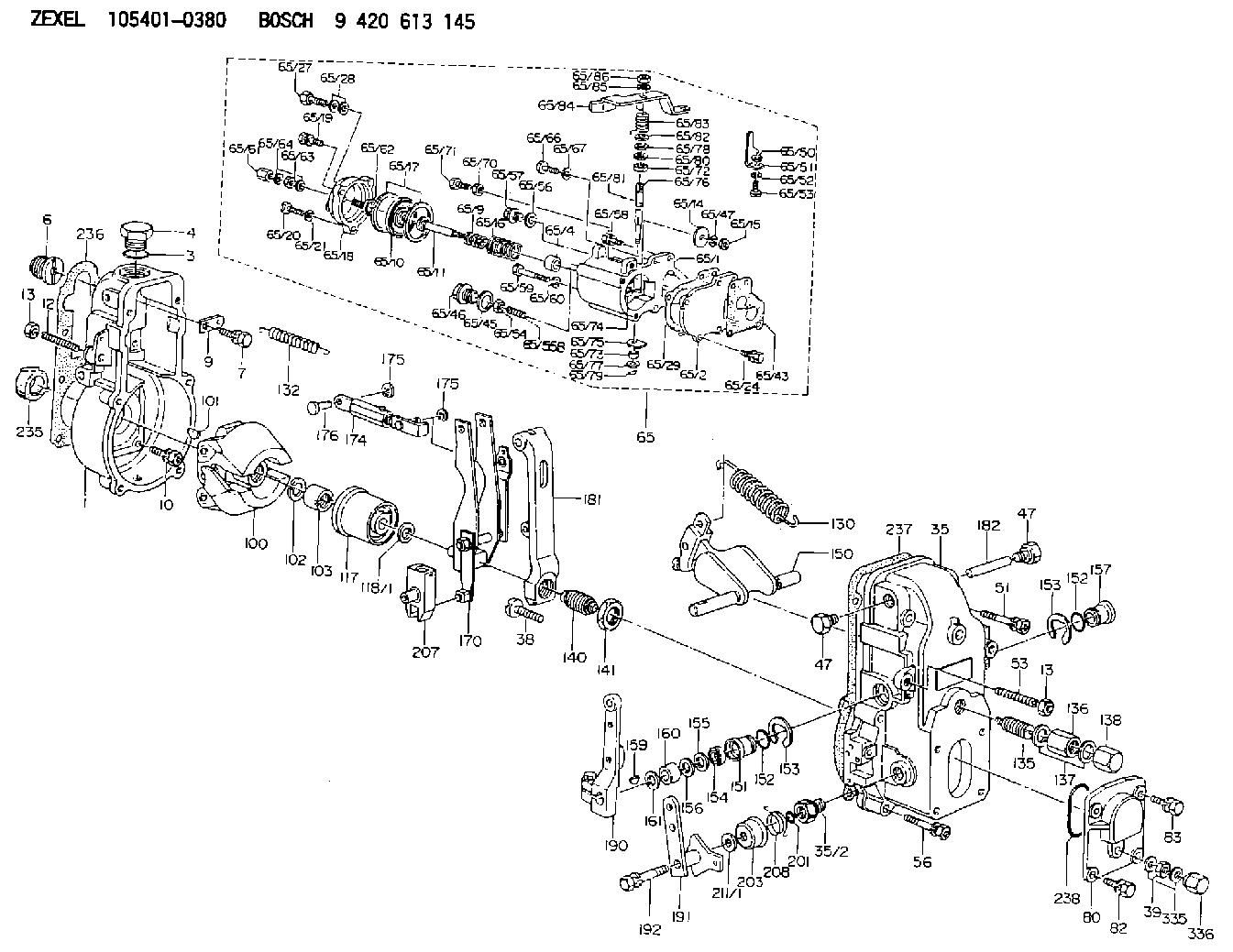
| 1. | [1] | 154000-6300 | GOVERNOR HOUSING |
| 3. | [1] | 029632-5070 | O-RING |
| 4. | [1] | 154007-2900 | CAPSULE |
| 6. | [1] | 154007-0200 | ADAPTOR |
| 7. | [1] | 020018-1840 | BLEEDER SCREW M8P1.25L18 |
| 9. | [1] | 154350-1900 | PLATE |
| 10. | [6] | 029010-6810 | BLEEDER SCREW |
| 12. | [1] | 154010-0100 | FLAT-HEAD SCREW |
| 13. | [2] | 154011-0100 | HEXAGON NUT |
| 13. | [2] | 154011-0100 | HEXAGON NUT |
| 35. | [1] | 154500-1020 | GOVERNOR COVER |
| 35/2. | [1] | 154321-0400 | BUSHING |
| 38. | [1] | 154031-2400 | FLAT-HEAD SCREW |
| 39. | [1] | 139206-0600 | UNION NUT |
| 47. | [2] | 154036-0300 | CAPSULE |
| 47. | [2] | 154036-0300 | CAPSULE |
| 51. | [2] | 020106-5040 | BLEEDER SCREW |
| 53. | [1] | 154010-0200 | FLAT-HEAD SCREW |
| 56. | [4] | 020106-3840 | BLEEDER SCREW |
| 65. | [1] | 154419-3520 | MANIFOLD-PRESSURE COMP. |
| 65/1. | [1] | 154412-6821 | DIAPHRAGM HOUSING |
| 65/2. | [1] | 154412-0401 | SPACER BUSHING |
| 65/4. | [1] | 154413-0500 | BUSHING |
| 65/9. | [1] | 154402-1900 | COILED SPRING |
| 65/10. | [1] | 154400-8220 | DIAPHRAGM |
| 65/11. | [1] | 154400-8400 | STOP PIN |
| 65/14. | [1] | 154406-5500 | SLOTTED WASHER |
| 65/15. | [1] | 013020-6040 | UNION NUT M6P1H5 |
| 65/16. | [1] | 154402-4800 | COILED SPRING |
| 65/17. | [2] | 154413-2600 | GASKET |
| 65/18. | [1] | 154404-5000 | COVER |
| 65/19. | [1] | 020106-2040 | BLEEDER SCREW M6P1L20 |
| 65/20. | [2] | 139006-7000 | BLEEDER SCREW |
| 65/21. | [2] | 014110-6440 | LOCKING WASHER |
| 65/24. | [2] | 020106-1640 | BLEEDER SCREW M6P1.0L14 |
| 65/27. | [1] | 029731-0180 | EYE BOLT |
| 65/28. | [2] | 026510-1340 | GASKET D13.4&10.2T1 |
| 65/29. | [1] | 154390-3700 | GASKET |
| 65/43. | [1] | 154390-3400 | GASKET |
| 65/45. | [1] | 029331-8040 | GASKET |
| 65/46. | [1] | 154406-5800 | FLAT-HEAD SCREW |
| 65/47. | [1] | 014110-6440 | LOCKING WASHER |
| 65/50. | [1] | 154406-6200 | SPACER BUSHING |
| 65/51. | [1] | 154406-8900 | PLATE |
| 65/52. | [1] | 014110-6440 | LOCKING WASHER |
| 65/53. | [1] | 154406-6400 | BLEEDER SCREW |
| 65/54. | [1] | 013020-6040 | UNION NUT M6P1H5 |
| 65/55B. | [1] | 154404-4800 | FLAT-HEAD SCREW |
| 65/56. | [1] | 029331-2130 | GASKET |
| 65/57. | [1] | 154406-6500 | FLAT-HEAD SCREW |
| 65/58. | [1] | 020106-2240 | BLEEDER SCREW |
| 65/59. | [2] | 010006-7040 | BLEEDER SCREW M6P1L70 |
| 65/60. | [2] | 014110-6440 | LOCKING WASHER |
| 65/61. | [1] | 154035-1600 | CAP NUT |
| 65/62. | [1] | 154404-4400 | FLAT-HEAD SCREW |
| 65/63. | [1] | 023040-6040 | UNION NUT |
| 65/64. | [2] | 026506-1040 | GASKET D9.9&6.2T1 |
| 65/66. | [1] | 139006-0900 | BLEEDER SCREW |
| 65/67. | [1] | 014110-6440 | LOCKING WASHER |
| 65/70. | [1] | 029240-6010 | UNION NUT M6P1.0H5* |
| 65/71. | [1] | 153141-1600 | BLEEDER SCREW |
| 65/72. | [1] | 139608-0000 | PACKING RING |
| 65/73. | [1] | 139605-0100 | PACKING RING |
| 65/74. | [1] | 154412-6900 | CONTROL LEVER |
| 65/75. | [1] | 154406-7500 | CONTROL LEVER |
| 65/76. | [1] | 154412-7000 | LEVER SHAFT |
| 65/77. | [1] | 029310-5200 | SHIM |
| 65/78. | [1] | 014020-8120 | PLAIN WASHER D16&8.5T1.2 |
| 65/79. | [1] | 154372-6500 | SAFETY PIN |
| 65/80. | [0] | 029310-8040 | SHIM D13.5&8T0.2 |
| 65/80B. | [0] | 029310-8050 | SHIM D13.5&8T0.5 |
| 65/81. | [1] | 025520-1210 | SPLIT PIN |
| 65/82. | [2] | 029300-8320 | SHIM |
| 65/83. | [1] | 154403-9900 | COILED SPRING |
| 65/84. | [1] | 154412-7100 | CONTROL LEVER |
| 65/85. | [1] | 014110-8440 | LOCKING WASHER |
| 65/86. | [1] | 013020-8140 | UNION NUT M8P1.25H6.5 |
| 80. | [1] | 154063-1400 | COVER |
| 82. | [2] | 029020-6210 | BLEEDER SCREW |
| 83. | [2] | 020006-1640 | BLEEDER SCREW M6P1L16 4T |
| 100. | [1] | 154100-9720 | FLYWEIGHT ASSEMBLY |
| 101. | [1] | 025803-1610 | WOODRUFF KEY |
| 102. | [1] | 029321-2020 | LOCKING WASHER |
| 103. | [1] | 029231-2030 | UNION NUT |
| 117. | [1] | 154123-2320 | SLIDING PIECE |
| 118/1. | [0] | 029311-0010 | SHIM D14&10.1T0.2 |
| 118/1. | [0] | 029311-0180 | SHIM D14&10.1T0.3 |
| 118/1. | [0] | 029311-0190 | SHIM D14&10.1T0.40 |
| 118/1. | [0] | 029311-0210 | SHIM D14&10.1T1 |
| 118/1. | [0] | 139410-0000 | SHIM D14.0&10.1T0.5 |
| 118/1. | [0] | 139410-0100 | SHIM D14.0&10.1T1.5 |
| 118/1. | [0] | 139410-3000 | SHIM D14&10.1T2.0 |
| 118/1. | [0] | 139410-3100 | SHIM D14&10.1T3.0 |
| 118/1. | [0] | 139410-3200 | SHIM D14&10.1T4.0 |
| 130. | [1] | 154150-6400 | GOVERNOR SPRING |
| 132. | [1] | 154154-0500 | COILED SPRING |
| 135. | [1] | 154158-0920 | HEADLESS SCREW |
| 136. | [1] | 154011-1700 | UNION NUT |
| 137. | [2] | 026512-1540 | GASKET D15.4&12.2T1.50 |
| 138. | [1] | 154159-1200 | CAP NUT |
| 140. | [1] | 154185-1320 | HEADLESS SCREW |
| 141. | [1] | 029201-6010 | UNION NUT |
| 150. | [1] | 154200-7020 | SWIVELLING LEVER |
| 151. | [1] | 154204-3000 | BUSHING |
| 152. | [2] | 029631-8020 | O-RING |
| 152. | [2] | 029631-8020 | O-RING |
| 152. | [2] | 029631-8020 | O-RING |
| 153. | [2] | 016010-1640 | LOCKING WASHER |
| 154. | [1] | 139611-0000 | PACKING RING |
| 155. | [1] | 139411-0000 | SHIM |
| 156. | [0] | 029311-1070 | SHIM D16&11T0.5 |
| 157. | [1] | 154204-3100 | BUSHING |
| 159. | [1] | 025803-1310 | WOODRUFF KEY |
| 160. | [1] | 154206-2800 | BUSHING |
| 161. | [0] | 154206-0200 | PLAIN WASHER D19.5&11.2T1.0 |
| 170. | [1] | 154210-0920 | FORK LEVER |
| 174. | [1] | 154230-4320 | STRAP |
| 175. | [2] | 016010-0540 | LOCKING WASHER |
| 175. | [2] | 016010-0540 | LOCKING WASHER |
| 176. | [1] | 154222-4300 | BEARING PIN |
| 181. | [1] | 154236-4100 | TENSIONING LEVER |
| 182. | [1] | 154237-0100 | BEARING PIN |
| 190. | [1] | 154309-6120 | CONTROL LEVER |
| 191. | [1] | 154365-9321 | CONTROL LEVER |
| 192. | [1] | 020006-4540 | BLEEDER SCREW M6P1L45 |
| 201. | [1] | 029631-0030 | O-RING &9.8W2.3 |
| 203. | [1] | 154322-0100 | CAP |
| 207. | [1] | 154326-5020 | CONTROL LEVER |
| 208. | [1] | 154327-7600 | COILED SPRING |
| 211/1. | [0] | 029311-0520 | SHIM D20.8&10.3T0.2 |
| 211/1. | [0] | 029311-0530 | SHIM D20.8&10.3T0.25 |
| 211/1. | [0] | 029311-0540 | SHIM D20.8&10.3T0.3 |
| 211/1. | [0] | 029311-0550 | SHIM D20.8&10.3T0.35 |
| 211/1. | [0] | 029311-0560 | SHIM D20.8&10.3T0.4 |
| 211/1. | [0] | 029311-0570 | SHIM D20.8&10.3T0.5 |
| 235. | [1] | 155412-5200 | IMPELLER WHEEL |
| 236. | [1] | 154390-0000 | GASKET |
| 237. | [1] | 154390-0300 | GASKET |
| 238. | [1] | 029635-2020 | O-RING |
| 335. | [2] | 026506-1040 | GASKET D9.9&6.2T1 |
| 336. | [1] | 154035-1600 | CAP NUT |
Include in #1:
101692-9290
as GOVERNOR
Cross reference number
Zexel num
Bosch num
Firm num
Name
Information:
Always determine the cause of the engine shutdown. Make necessary repairs before attempting restarting the engine.
Air Shutoff Solenoid (If Equipped)
This optional solenoid is located on top of the engine in the air inlet system. When the solenoid is activated, the solenoid mechanically shuts off inlet air to the engine. The solenoid can only be activated by the overspeed switch or the emergency stop switch.Fuel Shutoff Solenoid
This solenoid is located on the governor or on the fuel injection pump. When the solenoid is activated, the solenoid moves the fuel rack (either directly or through the governor) to the Fuel Off position.Overspeed Shutoffs
Magnetic pickup (1), mounted in the flywheel housing (2).A magnetic pickup mounted in the flywheel housing senses the passage of the flywheel ring gear teeth. Should the engine speed increase above the overspeed setting of the Electronic Speed Switch (118 percent of rated engine speed), the magnetic pickup will sense the overspeed. The overspeed condition activates both the air (if equipped) and fuel shutoff solenoids.The shutoffs must be reset before the engine will restart. A reset button on the Electronic Speed Switch (in the junction box) must be pushed to open the overspeed switch. The air shutoff lever (at the top of the air inlet housing) must be manually reset.Oil Pressure Switches
Typical example of oil pressure switches, mounted in the rear of the junction box.An oil pressure switch has wires connected to the electrical system for alarm or shutoff functions. The oil pressure switch senses oil pressure at the bearing oil gallery. If sufficient oil pressure is not achieved after engine starting, or if the engine has been running normally and then loses oil pressure, the fuel shutoff solenoid is energized to shut the engine off. No resetting procedure is required.Engine Step Oil Pressure
This is an adjustable engine speed setting that protects the engine from a failure caused by too little oil pressure for a specified speed range. This option requires two different oil pressure switches. One switch has a high pressure rating- when the engine is running above the speed setting, the engine must maintain oil pressure higher than the switch rating. The other switch has a low pressure rating- an engine running below the speed setting must maintain oil pressure above the low switch rating.In an automatic start/stop system, an automatic reset switch is used. Manually operated systems require the switch to be reset before the engine will start.
If the RESET button does not move to the extended position after the engine starts, the engine will NOT be protected by this particular switch.If the RESET button remains in the reset position, the engine oil pump will not develop normal oil pressure. An inspection should be made to correct the problem.
In order to reset the switch, push the RESET button until the button latches. After the engine starts and develops oil pressure, the button will move to the extended (running) position.
The button must be in the RUN position to protect the engine. If the button remains in