Information governor
BOSCH
9 420 614 139
9420614139
ZEXEL
105401-0341
1054010341

Rating:
Scheme ###:
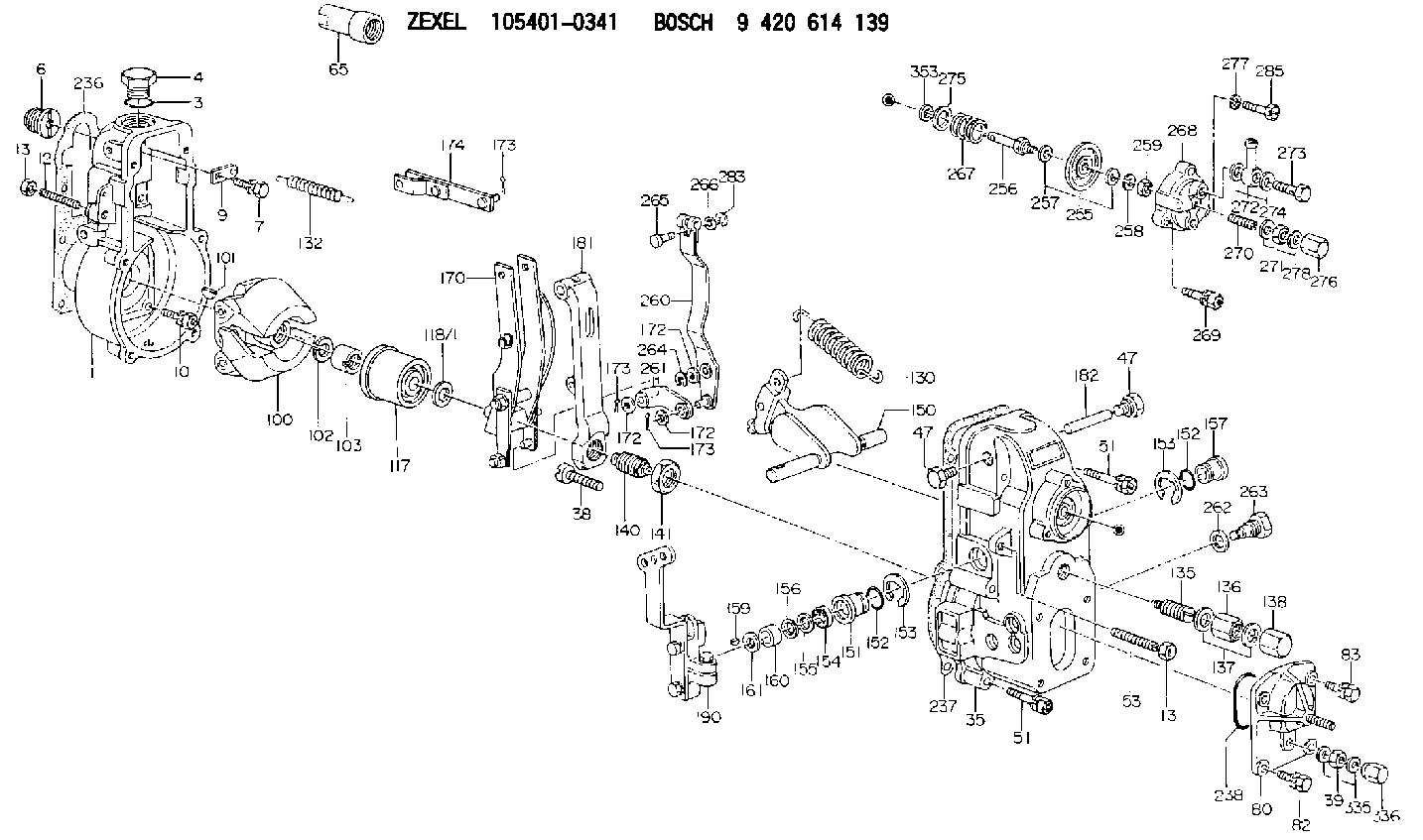
| 1. | [1] | 154000-6300 | GOVERNOR HOUSING |
| 3. | [1] | 029632-5070 | O-RING |
| 4. | [1] | 154007-2900 | CAPSULE |
| 6. | [1] | 154007-0200 | ADAPTOR |
| 7. | [1] | 020018-1840 | BLEEDER SCREW M8P1.25L18 |
| 9. | [1] | 154350-1900 | PLATE |
| 10. | [6] | 029010-6810 | BLEEDER SCREW |
| 12. | [1] | 154010-0100 | FLAT-HEAD SCREW |
| 13. | [2] | 154011-0100 | HEXAGON NUT |
| 13. | [2] | 154011-0100 | HEXAGON NUT |
| 35. | [1] | 154022-5320 | GOVERNOR COVER |
| 38. | [1] | 154031-1300 | FLAT-HEAD SCREW |
| 39. | [1] | 139206-0600 | UNION NUT |
| 47. | [2] | 154036-0300 | CAPSULE |
| 47. | [2] | 154036-0300 | CAPSULE |
| 51. | [6] | 020106-5040 | BLEEDER SCREW |
| 51. | [6] | 020106-5040 | BLEEDER SCREW |
| 53. | [1] | 154010-0300 | FLAT-HEAD SCREW |
| 65. | [1] | 154050-1720 | STOPPING DEVICE |
| 80. | [1] | 154063-6820 | COVER |
| 82. | [2] | 029020-6210 | BLEEDER SCREW |
| 83. | [2] | 020006-1640 | BLEEDER SCREW M6P1L16 4T |
| 100. | [1] | 154101-0120 | FLYWEIGHT |
| 101. | [1] | 025803-1610 | WOODRUFF KEY |
| 102. | [1] | 029321-2020 | LOCKING WASHER |
| 103. | [1] | 029231-2030 | UNION NUT |
| 117. | [1] | 154123-0120 | SLIDING PIECE |
| 118/1. | [0] | 029311-0010 | SHIM D14&10.1T0.2 |
| 118/1. | [0] | 029311-0180 | SHIM D14&10.1T0.3 |
| 118/1. | [0] | 029311-0190 | SHIM D14&10.1T0.40 |
| 118/1. | [0] | 029311-0210 | SHIM D14&10.1T1 |
| 118/1. | [0] | 139410-0000 | SHIM D14.0&10.1T0.5 |
| 118/1. | [0] | 139410-0100 | SHIM D14.0&10.1T1.5 |
| 118/1. | [0] | 139410-3000 | SHIM D14&10.1T2.0 |
| 118/1. | [0] | 139410-3100 | SHIM D14&10.1T3.0 |
| 118/1. | [0] | 139410-3200 | SHIM D14&10.1T4.0 |
| 130. | [1] | 154150-0400 | GOVERNOR SPRING |
| 132. | [1] | 154154-1200 | COILED SPRING |
| 135. | [1] | 154158-1520 | HEADLESS SCREW |
| 136. | [1] | 029201-2140 | UNION NUT |
| 137. | [2] | 026512-1540 | GASKET D15.4&12.2T1.50 |
| 138. | [1] | 154159-1200 | CAP NUT |
| 140. | [1] | 154177-2120 | HEADLESS SCREW |
| 141. | [1] | 029201-6010 | UNION NUT |
| 150. | [1] | 154200-7020 | SWIVELLING LEVER |
| 151. | [1] | 154204-3000 | BUSHING |
| 152. | [2] | 029631-8020 | O-RING |
| 152. | [2] | 029631-8020 | O-RING |
| 153. | [2] | 016010-1640 | LOCKING WASHER |
| 153. | [2] | 016010-1640 | LOCKING WASHER |
| 154. | [1] | 139611-0000 | PACKING RING |
| 155. | [1] | 139411-0000 | SHIM |
| 156. | [0] | 029311-1070 | SHIM D16&11T0.5 |
| 157. | [1] | 154204-3100 | BUSHING |
| 159. | [1] | 025803-1310 | WOODRUFF KEY |
| 160. | [1] | 154206-2800 | BUSHING |
| 161. | [0] | 154206-0200 | PLAIN WASHER D19.5&11.2T1.0 |
| 170. | [1] | 154211-4120 | FORK LEVER |
| 172. | [3] | 029310-5170 | SHIM D8&5.3T0.5 |
| 172. | [3] | 029310-5170 | SHIM D8&5.3T0.5 |
| 172. | [3] | 029310-5170 | SHIM D8&5.3T0.5 |
| 173. | [3] | 025520-1210 | SPLIT PIN |
| 173. | [3] | 025520-1210 | SPLIT PIN |
| 173. | [3] | 025520-1210 | SPLIT PIN |
| 174. | [1] | 154230-0120 | STRAP |
| 181. | [1] | 154236-4100 | TENSIONING LEVER |
| 182. | [1] | 154237-0100 | BEARING PIN |
| 190. | [1] | 154343-9220 | CONTROL LEVER |
| 236. | [1] | 154390-0000 | GASKET |
| 237. | [1] | 154390-0300 | GASKET |
| 238. | [1] | 029635-2020 | O-RING |
| 255. | [1] | 154400-0520 | DIAPHRAGM |
| 256. | [1] | 154400-4800 | STOP PIN |
| 257. | [2] | 029330-8050 | GASKET |
| 258. | [1] | 139308-0700 | LOCKING WASHER |
| 259. | [1] | 013030-6040 | UNION NUT M6P1H3.6 |
| 260. | [1] | 154401-0220 | CONTROL LEVER |
| 261. | [1] | 154401-1320 | STRAP |
| 262. | [1] | 026510-1440 | GASKET D13.9&10.2T1 |
| 263. | [1] | 154401-2100 | BLEEDER SCREW |
| 264. | [1] | 016010-0540 | LOCKING WASHER |
| 265. | [1] | 154222-6200 | BEARING PIN |
| 266. | [1] | 029300-4010 | PLAIN WASHER |
| 267. | [1] | 154402-4500 | COILED SPRING |
| 268. | [1] | 154404-5000 | COVER |
| 269. | [2] | 020106-2540 | BLEEDER SCREW M6P1L25 |
| 270. | [1] | 154404-1100 | FLAT-HEAD SCREW |
| 271. | [1] | 023040-6040 | UNION NUT |
| 272. | [1] | 029711-0140 | INLET UNION |
| 273. | [1] | 029731-0180 | EYE BOLT |
| 274. | [2] | 029341-0110 | GASKET |
| 275. | [0] | 029312-0180 | SHIM D25.5&20T0.5 |
| 275B. | [0] | 029312-0210 | SHIM D25.5&20T0.2 |
| 276. | [1] | 154035-0320 | CAP NUT |
| 277. | [1] | 014110-6440 | LOCKING WASHER |
| 278. | [2] | 154413-2600 | GASKET |
| 283. | [1] | 016010-0440 | LOCKING WASHER |
| 285. | [1] | 029010-6310 | BLEEDER SCREW |
| 335. | [2] | 026506-1040 | GASKET D9.9&6.2T1 |
| 336. | [1] | 154035-1600 | CAP NUT |
| 353. | [2] | 029310-9080 | SHIM D16&9T1.7 |
Include in #1:
101692-3851
as GOVERNOR
Cross reference number
Zexel num
Bosch num
Firm num
Name
Information:
Torque for Standard Bolts, Nuts and Taperlock Studs
The following charts give general torques for bolts, nuts, and taperlock studs. For torque specifications not included in this section, refer to Torque Specifications, SENR3130, available from your Caterpillar dealer.
Torques for Bolts and Nuts With Standard Threads
Torques for Taperlock Studs
Use these standard torque values for all fasteners, unless otherwise specified in this manual or in the Service Manual.Torque for Metric Fasteners
Be very careful never to mix metric with customary (SAE standard) fasteners. Mismatched or incorrect fasteners will cause engine damage or malfunction and may even result in personal injury.Original fasteners removed from the engine should be saved for reassembly whenever possible. If new fasteners are needed, they must be of the same size and grade as the ones that are being replaced.
Material strength identification is usually shown on the bolt head by numbers (8.8, 10.9, etc.). The following chart gives general torque values for bolts and nuts. Use these standard torque values unless otherwise specified in this publication. Metric hardware must be replaced with metric hardware. Check Parts Manual for proper replacement.Torques for Bolts and Nuts with Metric Threads
Torque for Standard Hose Clamps-Worm Drive Band Type
The following chart gives the torques for initial installation of hose clamps on new hose and for reassembly or tightening of hose clamps on existing hose. Torque for Constant Torque Hose Clamps
Due to extreme temperature changes, hose will heat set. Heat settings causes hose clamps to loosen. Loose hose clamps can result in leaks. There have been reports of component failures caused by hose clamps loosening. The new constant torque hose clamp will help prevent these failures. A constant torque hose clamp can be used in place of any standard hose clamp. Make sure the constant torque hose clamp is the same size as the standard clamp.
Installation
Each installation application can be different depending on the type of hose, fitting material, and anticipated expansion or contraction of the hose and fittings. A torque wrench should be used for proper installation of constant torque hose clamps. Constant torque hose clamps should be installed as follows:* To allow for maximum expansion, install clamps at 5.7 N m (50 lb in).* To allow for equal expansion and contraction, install clamps at 10.2 N m (90 lb in).* To allow for maximum contraction, install clamps at 14.1 N m (125 lb in).