Information governor
BOSCH
9 420 614 138
9420614138
ZEXEL
105401-0331
1054010331
Rating:
Scheme ###:
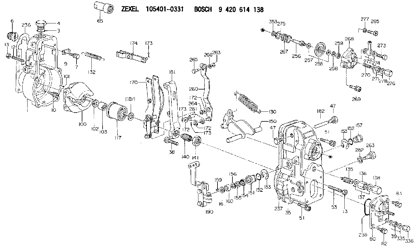
| 1. | [1] | 154000-6300 | GOVERNOR HOUSING |
| 3. | [1] | 029632-5070 | O-RING |
| 4. | [1] | 154007-2900 | CAPSULE |
| 6. | [1] | 154007-0200 | ADAPTOR |
| 7. | [1] | 020018-1840 | BLEEDER SCREW M8P1.25L18 |
| 9. | [1] | 154350-1900 | PLATE |
| 10. | [6] | 029010-6810 | BLEEDER SCREW |
| 12. | [1] | 154010-0100 | FLAT-HEAD SCREW |
| 13. | [2] | 154011-0100 | HEXAGON NUT |
| 13. | [2] | 154011-0100 | HEXAGON NUT |
| 35. | [1] | 154022-5320 | GOVERNOR COVER |
| 38. | [1] | 154031-1300 | FLAT-HEAD SCREW |
| 39. | [1] | 139206-0600 | UNION NUT |
| 47. | [2] | 154036-0300 | CAPSULE |
| 47. | [2] | 154036-0300 | CAPSULE |
| 51. | [6] | 020106-5040 | BLEEDER SCREW |
| 51. | [6] | 020106-5040 | BLEEDER SCREW |
| 53. | [1] | 154010-0300 | FLAT-HEAD SCREW |
| 65. | [1] | 154050-1720 | STOPPING DEVICE |
| 80. | [1] | 154063-6820 | COVER |
| 82. | [2] | 029020-6210 | BLEEDER SCREW |
| 83. | [2] | 020006-1640 | BLEEDER SCREW M6P1L16 4T |
| 100. | [1] | 154101-0120 | FLYWEIGHT |
| 101. | [1] | 025803-1610 | WOODRUFF KEY |
| 102. | [1] | 029321-2020 | LOCKING WASHER |
| 103. | [1] | 029231-2030 | UNION NUT |
| 117. | [1] | 154123-0120 | SLIDING PIECE |
| 118/1. | [0] | 029311-0010 | SHIM D14&10.1T0.2 |
| 118/1. | [0] | 029311-0180 | SHIM D14&10.1T0.3 |
| 118/1. | [0] | 029311-0190 | SHIM D14&10.1T0.40 |
| 118/1. | [0] | 029311-0210 | SHIM D14&10.1T1 |
| 118/1. | [0] | 139410-0000 | SHIM D14.0&10.1T0.5 |
| 118/1. | [0] | 139410-0100 | SHIM D14.0&10.1T1.5 |
| 118/1. | [0] | 139410-3000 | SHIM D14&10.1T2.0 |
| 118/1. | [0] | 139410-3100 | SHIM D14&10.1T3.0 |
| 118/1. | [0] | 139410-3200 | SHIM D14&10.1T4.0 |
| 130. | [1] | 154150-0400 | GOVERNOR SPRING |
| 132. | [1] | 154154-1200 | COILED SPRING |
| 135. | [1] | 154158-1520 | HEADLESS SCREW |
| 136. | [1] | 029201-2140 | UNION NUT |
| 137. | [2] | 026512-1540 | GASKET D15.4&12.2T1.50 |
| 138. | [1] | 154159-1200 | CAP NUT |
| 140. | [1] | 154177-1520 | HEADLESS SCREW |
| 141. | [1] | 029201-6010 | UNION NUT |
| 150. | [1] | 154200-7020 | SWIVELLING LEVER |
| 151. | [1] | 154204-3000 | BUSHING |
| 152. | [2] | 029631-8020 | O-RING |
| 152. | [2] | 029631-8020 | O-RING |
| 153. | [2] | 016010-1640 | LOCKING WASHER |
| 153. | [2] | 016010-1640 | LOCKING WASHER |
| 154. | [1] | 139611-0000 | PACKING RING |
| 155. | [1] | 139411-0000 | SHIM |
| 156. | [0] | 029311-1070 | SHIM D16&11T0.5 |
| 157. | [1] | 154204-3100 | BUSHING |
| 159. | [1] | 025803-1310 | WOODRUFF KEY |
| 160. | [1] | 154206-2800 | BUSHING |
| 161. | [0] | 154206-0200 | PLAIN WASHER D19.5&11.2T1.0 |
| 170. | [1] | 154211-4120 | FORK LEVER |
| 172. | [3] | 029310-5170 | SHIM D8&5.3T0.5 |
| 172. | [3] | 029310-5170 | SHIM D8&5.3T0.5 |
| 172. | [3] | 029310-5170 | SHIM D8&5.3T0.5 |
| 173. | [3] | 025520-1210 | SPLIT PIN |
| 173. | [3] | 025520-1210 | SPLIT PIN |
| 173. | [3] | 025520-1210 | SPLIT PIN |
| 174. | [1] | 154230-0120 | STRAP |
| 181. | [1] | 154236-4100 | TENSIONING LEVER |
| 182. | [1] | 154237-0100 | BEARING PIN |
| 190. | [1] | 154343-9220 | CONTROL LEVER |
| 236. | [1] | 154390-0000 | GASKET |
| 237. | [1] | 154390-0300 | GASKET |
| 238. | [1] | 029635-2020 | O-RING |
| 255. | [1] | 154400-0520 | DIAPHRAGM |
| 256. | [1] | 154400-4800 | STOP PIN |
| 257. | [2] | 029330-8050 | GASKET |
| 258. | [1] | 139308-0700 | LOCKING WASHER |
| 259. | [1] | 013030-6040 | UNION NUT M6P1H3.6 |
| 260. | [1] | 154401-0220 | CONTROL LEVER |
| 261. | [1] | 154401-1320 | STRAP |
| 262. | [1] | 026510-1440 | GASKET D13.9&10.2T1 |
| 263. | [1] | 154401-2100 | BLEEDER SCREW |
| 264. | [1] | 016010-0540 | LOCKING WASHER |
| 265. | [1] | 154222-6200 | BEARING PIN |
| 266. | [1] | 029300-4010 | PLAIN WASHER |
| 267. | [1] | 154402-4500 | COILED SPRING |
| 268. | [1] | 154404-5000 | COVER |
| 269. | [2] | 020106-2540 | BLEEDER SCREW M6P1L25 |
| 270. | [1] | 154404-1100 | FLAT-HEAD SCREW |
| 271. | [1] | 023040-6040 | UNION NUT |
| 272. | [1] | 029711-0140 | INLET UNION |
| 273. | [1] | 029731-0180 | EYE BOLT |
| 274. | [2] | 029341-0110 | GASKET |
| 275. | [0] | 029312-0180 | SHIM D25.5&20T0.5 |
| 275B. | [0] | 029312-0210 | SHIM D25.5&20T0.2 |
| 276. | [1] | 154035-0320 | CAP NUT |
| 277. | [1] | 014110-6440 | LOCKING WASHER |
| 278. | [2] | 154413-2600 | GASKET |
| 283. | [1] | 016010-0440 | LOCKING WASHER |
| 285. | [1] | 029010-6310 | BLEEDER SCREW |
| 335. | [2] | 026506-1040 | GASKET D9.9&6.2T1 |
| 336. | [1] | 154035-1600 | CAP NUT |
| 353. | [2] | 029310-9080 | SHIM D16&9T1.7 |
Include in #1:
101692-3841
as GOVERNOR
Cross reference number
Zexel num
Bosch num
Firm num
Name
Information:
Engine Lifting
When it is necessary to remove a component on an angle, remember that the capacity of an eyebolt is less as the angle between the supporting members and the object becomes less than 90 degrees. Eye Bolts and brackets should never be bent, and should only be loaded under tension.
Use a hoist to remove heavy components. Use an adjustable lifting beam to lift the engine. All supporting members (chains and cables) should be parallel to each other, and perpendicular as possible to the top of the object being lifted.Some removals require the use of lifting fixtures, to obtain proper balance and provide safe handling.To remove the engine ONLY, use the lifting eyes equipped with the engine.The lifting eyes are designed for the engine arrangement as sold. Modifying the lifting eyes and/or engine arrangement weight renders the lifting eyes and devices obsolete.If you modify the lifting eyes and/or engine arrangement weight, you are responsible for providing adequate lifting devices. Contact your Caterpillar dealer for information regarding fixtures for proper engine package lifting.Engine Lifting With Fuel Tank
Lifting the engine along with a mounted fuel tank requires special equipment and procedures. Do not lift the unit with fuel in the tank. Contact your Caterpillar dealer for information regarding proper engine and fuel tank lifting.Engine Storage
The following Engine Storage procedures and recommendations minimize the possibility of damage to engines stored for one year or less.When an engine is not started for several weeks, the lubricating oil drains from the cylinder walls and piston rings. Rust can then form on the cylinder liner surface, increasing engine wear and decreasing engine life.Special precautions should be used with engines remaining out of service for extended periods.After one year, a complete protection procedure must be followed if the engine is kept in storage longer. To prevent excessive engine wear:* Be sure all lubrication recommendations mentioned in the Maintenance Schedule intervals chart are completed.* If freezing temperatures are expected, check the cooling system for adequate protection against freezing. A 50/50 solution of Caterpillar (permanent-type) Antifreeze and approved water will give protection to -29°C (-20°F).If it will be impossible to start the engine periodically, consult your Caterpillar dealer for instructions to prepare your engine for longer storage periods.Refer to Storage Procedures For Caterpillar Products, SEHS9031, for more detailed information on engine storage.