Information governor
BOSCH
F 019 Z2E 593
f019z2e593
ZEXEL
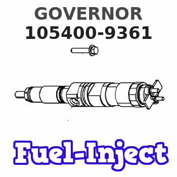
105400-9361
1054009361
ISUZU
8972874210
8972874210
Rating:
Scheme ###:
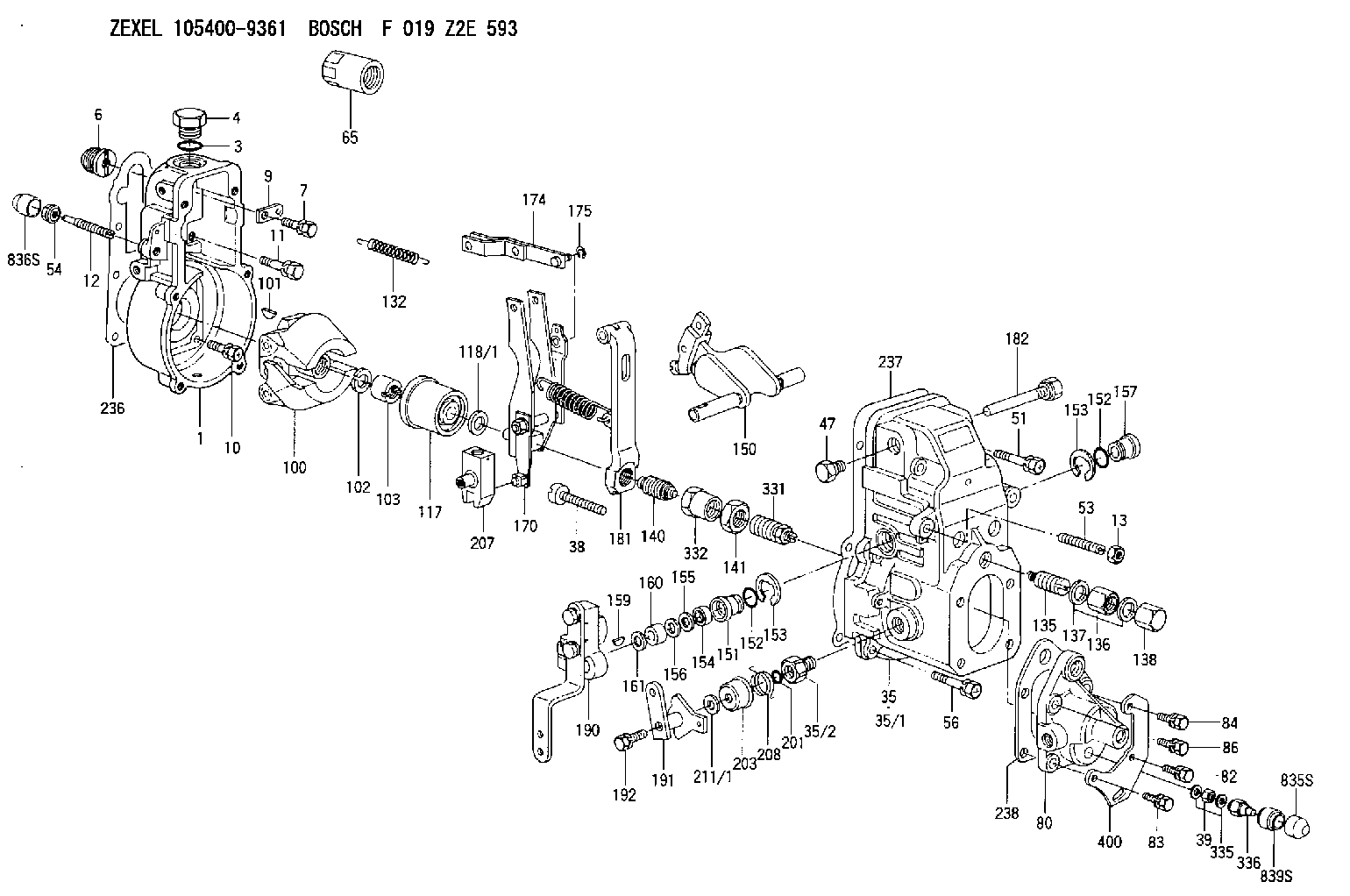
| 1. | [1] | 154000-6300 | GOVERNOR HOUSING |
| 3. | [1] | 029632-5070 | O-RING |
| 4. | [1] | 154007-2900 | CAPSULE |
| 6. | [1] | 154007-0200 | ADAPTOR |
| 7. | [1] | 020018-1840 | BLEEDER SCREW M8P1.25L18 |
| 9. | [1] | 154350-1800 | PLATE |
| 10. | [5] | 029010-6810 | BLEEDER SCREW |
| 11. | [1] | 020106-1640 | BLEEDER SCREW M6P1.0L14 |
| 12. | [1] | 154013-5000 | FLAT-HEAD SCREW |
| 13. | [1] | 154011-0100 | HEXAGON NUT |
| 35. | [1] | 154501-1520 | GOVERNOR COVER |
| 35/1. | [1] | 154501-1500 | GOVERNOR COVER |
| 35/2. | [1] | 154321-0400 | BUSHING |
| 38. | [1] | 154031-4700 | FLAT-HEAD SCREW |
| 39. | [1] | 139208-0400 | UNION NUT |
| 47. | [1] | 154036-0300 | CAPSULE |
| 51. | [2] | 020106-5040 | BLEEDER SCREW |
| 53. | [1] | 154010-0100 | FLAT-HEAD SCREW |
| 54. | [1] | 154011-4900 | UNION NUT |
| 56. | [4] | 020106-3840 | BLEEDER SCREW |
| 65. | [1] | 155404-5700 | CAP |
| 80. | [1] | 154064-4200 | COVER |
| 82. | [1] | 020006-2040 | BLEEDER SCREW M6P1L20 4T |
| 83. | [1] | 020006-2040 | BLEEDER SCREW M6P1L20 4T |
| 84. | [1] | 020006-2040 | BLEEDER SCREW M6P1L20 4T |
| 86. | [1] | 020006-1640 | BLEEDER SCREW M6P1L16 4T |
| 100. | [1] | 154101-0020 | FLYWEIGHT ASSEMBLY |
| 101. | [1] | 025803-1610 | WOODRUFF KEY |
| 102. | [1] | 029321-2020 | LOCKING WASHER |
| 103. | [1] | 029231-2030 | UNION NUT |
| 117. | [1] | 154123-2320 | SLIDING PIECE |
| 118/1. | [0] | 029311-0010 | SHIM D14&10.1T0.2 |
| 118/1. | [0] | 029311-0180 | SHIM D14&10.1T0.3 |
| 118/1. | [0] | 029311-0190 | SHIM D14&10.1T0.40 |
| 118/1. | [0] | 029311-0210 | SHIM D14&10.1T1 |
| 118/1. | [0] | 139410-0000 | SHIM D14.0&10.1T0.5 |
| 118/1. | [0] | 139410-0100 | SHIM D14.0&10.1T1.5 |
| 118/1. | [0] | 139410-3000 | SHIM D14&10.1T2.0 |
| 118/1. | [0] | 139410-3100 | SHIM D14&10.1T3.0 |
| 118/1. | [0] | 139410-3200 | SHIM D14&10.1T4.0 |
| 132. | [1] | 154154-0701 | COILED SPRING |
| 135. | [1] | 154158-1520 | HEADLESS SCREW |
| 136. | [1] | 029201-2130 | UNION NUT M12P1.0H6 |
| 137. | [2] | 026512-1540 | GASKET D15.4&12.2T1.50 |
| 138. | [1] | 154159-1200 | CAP NUT |
| 140. | [1] | 154185-4520 | HEADLESS SCREW |
| 141. | [1] | 029201-6130 | UNION NUT |
| 150. | [1] | 154200-7120 | SWIVELLING LEVER |
| 151. | [1] | 154204-4300 | BUSHING |
| 152. | [2] | 139718-0600 | O-RING |
| 152. | [2] | 139718-0600 | O-RING |
| 153. | [2] | 016010-1640 | LOCKING WASHER |
| 153. | [2] | 016010-1640 | LOCKING WASHER |
| 154. | [1] | 139611-0400 | PACKING RING |
| 155. | [1] | 139411-0000 | SHIM |
| 156. | [0] | 029311-1070 | SHIM D16&11T0.5 |
| 157. | [1] | 154204-4400 | BUSHING |
| 159. | [1] | 025803-1310 | WOODRUFF KEY |
| 160. | [1] | 154206-2800 | BUSHING |
| 161. | [0] | 154206-0200 | PLAIN WASHER D19.5&11.2T1.0 |
| 170. | [1] | 154218-7720 | FORK LEVER |
| 174. | [1] | 154230-3920 | STRAP |
| 175. | [1] | 016010-0540 | LOCKING WASHER |
| 181. | [1] | 154239-5720 | TENSIONING LEVER |
| 182. | [1] | 154237-1100 | BEARING PIN |
| 190. | [1] | 154396-4220 | CONTROL LEVER |
| 191. | [1] | 154383-3320 | CONTROL LEVER |
| 192. | [1] | 020006-4040 | BLEEDER SCREW |
| 201. | [1] | 139710-0300 | O-RING |
| 203. | [1] | 154322-0100 | CAP |
| 207. | [1] | 154326-5020 | CONTROL LEVER |
| 208. | [1] | 154327-7600 | COILED SPRING |
| 211/1. | [0] | 029311-0520 | SHIM D20.8&10.3T0.2 |
| 211/1. | [0] | 029311-0530 | SHIM D20.8&10.3T0.25 |
| 211/1. | [0] | 029311-0540 | SHIM D20.8&10.3T0.3 |
| 211/1. | [0] | 029311-0550 | SHIM D20.8&10.3T0.35 |
| 211/1. | [0] | 029311-0560 | SHIM D20.8&10.3T0.4 |
| 211/1. | [0] | 029311-0570 | SHIM D20.8&10.3T0.5 |
| 236. | [1] | 154390-0000 | GASKET |
| 237. | [1] | 154390-0300 | GASKET |
| 238. | [1] | 154390-5000 | GASKET |
| 331. | [1] | 154179-1820 | HEADLESS SCREW |
| 332. | [1] | 029201-6010 | UNION NUT |
| 335. | [2] | 026508-1140 | GASKET D11.4&8.2T1 |
| 336. | [1] | 154035-2900 | CAP NUT |
| 400. | [1] | 154376-3000 | BRACKET |
| 835S. | [1] | 154062-4020 | CAP |
| 836S. | [1] | 154062-3520 | CAP |
| 839S. | [1] | 154062-3900 | ADAPTOR |
Include in #1:
101402-7871
as GOVERNOR
Cross reference number
Zexel num
Bosch num
Firm num
Name
105400-9361
8972874210 ISUZU
GOVERNOR
K 14JB MECHANICAL GOVERNOR GOV RSV GOV
K 14JB MECHANICAL GOVERNOR GOV RSV GOV
Information:
Lubricant Viscosity Recommendations
The proper SAE grade of oil to select is determined by the minimum outside temperature at which the engine will be started and the maximum outside temperature in which the engine will be operating. This recommendation is to ensure the correct viscosity is used until the next oil change. Engine start-up at lower than specified ambient temperature requires caution. Start-up at very low ambient temperatures may require a jacket water heater, auxiliary oil heaters or other methods to increase the engine crankcase and surrounding temperatures. When operating below -20°C (-4°F) refer to Caterpillar for information.The use of multi-viscosity oils is preferred because of full protection through a wider temperature range. See chart for recommended viscosity and temperature range. To determine if the oil in the crankcase will flow in cold weather, remove the oil dipstick before starting. If the oil will flow off, the oil is fluid enough to circulate properly.Lubricant Viscosity Chart
Refill Capacities
Engine Crankcase Oil Capacity
The crankcase refill capacities reflect the engine crankcase capacity plus on-engine oil filter change. If equipped with an auxiliary oil filter system, consult the oil filter system manufacturer for information.Total Cooling System Capacity
The Total Cooling System capacity will vary, depending on the engine model (3114 or 3116), radiator system size and capacity provided by truck/vehicle manufacturer. In order to properly maintain the cooling system, Total Cooling System capacity must be known. The chart below is left blank and should be filled in by the customer to determine the Total Cooling System Capacity for his engine and application.Add 0.25 liter (0.5 U.S. pint) of Caterpillar liquid supplemental coolant additive (Conditioner) for every 30 liter (8 U.S. gallon) of cooling system capacity to maintain the cooling system at Every 250 Service Hours.