Information governor
BOSCH
9 420 614 945
9420614945
ZEXEL
105400-8932
1054008932
MITSUBISHI
ME755381
me755381

Rating:
Scheme ###:
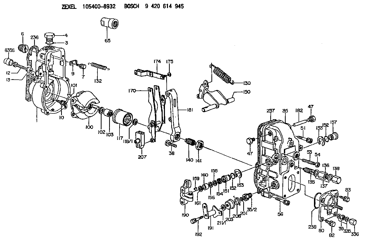
| 1. | [1] | 154000-6300 | GOVERNOR HOUSING |
| 3. | [1] | 029632-5070 | O-RING |
| 4. | [1] | 154007-2900 | CAPSULE |
| 6. | [1] | 154007-0200 | ADAPTOR |
| 7. | [1] | 020018-1840 | BLEEDER SCREW M8P1.25L18 |
| 9. | [1] | 154350-1900 | PLATE |
| 10. | [6] | 029010-6810 | BLEEDER SCREW |
| 12. | [1] | 154010-7200 | BLEEDER SCREW M8P1.25L62 |
| 12B. | [1] | 154010-8100 | BLEEDER SCREW M8P1.25L65 |
| 13. | [1] | 154011-0100 | HEXAGON NUT |
| 35. | [1] | 154500-1020 | GOVERNOR COVER |
| 35/2. | [1] | 154321-0400 | BUSHING |
| 38. | [1] | 154031-2400 | FLAT-HEAD SCREW |
| 39. | [1] | 139206-0600 | UNION NUT |
| 47. | [2] | 154036-0300 | CAPSULE |
| 47. | [2] | 154036-0300 | CAPSULE |
| 51. | [2] | 020106-5040 | BLEEDER SCREW |
| 53. | [1] | 154010-0200 | FLAT-HEAD SCREW |
| 54. | [1] | 154011-2300 | UNION NUT |
| 56. | [4] | 020106-3840 | BLEEDER SCREW |
| 65. | [1] | 154050-6120 | STOPPING DEVICE |
| 80. | [1] | 154063-5420 | COVER |
| 82. | [2] | 029020-6210 | BLEEDER SCREW |
| 83. | [2] | 020006-1640 | BLEEDER SCREW M6P1L16 4T |
| 100. | [1] | 154101-0020 | FLYWEIGHT ASSEMBLY |
| 101. | [1] | 025803-1610 | WOODRUFF KEY |
| 102. | [1] | 029321-2020 | LOCKING WASHER |
| 103. | [1] | 029231-2030 | UNION NUT |
| 117. | [1] | 154123-2320 | SLIDING PIECE |
| 118/1. | [0] | 029311-0010 | SHIM D14&10.1T0.2 |
| 118/1. | [0] | 029311-0180 | SHIM D14&10.1T0.3 |
| 118/1. | [0] | 029311-0190 | SHIM D14&10.1T0.40 |
| 118/1. | [0] | 029311-0210 | SHIM D14&10.1T1 |
| 118/1. | [0] | 139410-0000 | SHIM D14.0&10.1T0.5 |
| 118/1. | [0] | 139410-0100 | SHIM D14.0&10.1T1.5 |
| 118/1. | [0] | 139410-3000 | SHIM D14&10.1T2.0 |
| 118/1. | [0] | 139410-3100 | SHIM D14&10.1T3.0 |
| 118/1. | [0] | 139410-3200 | SHIM D14&10.1T4.0 |
| 130. | [1] | 154150-2900 | GOVERNOR SPRING |
| 132. | [1] | 154154-0701 | COILED SPRING |
| 135. | [1] | 154158-5020 | HEADLESS SCREW |
| 136. | [1] | 154011-4400 | UNION NUT |
| 137. | [2] | 026512-1540 | GASKET D15.4&12.2T1.50 |
| 138. | [1] | 154412-5300 | CAP NUT |
| 140. | [1] | 154177-0820 | HEADLESS SCREW |
| 141. | [1] | 029201-6010 | UNION NUT |
| 150. | [1] | 154200-7020 | SWIVELLING LEVER |
| 151. | [1] | 154204-4300 | BUSHING |
| 152. | [2] | 029631-8020 | O-RING |
| 152. | [2] | 029631-8020 | O-RING |
| 153. | [2] | 016010-1640 | LOCKING WASHER |
| 153. | [2] | 016010-1640 | LOCKING WASHER |
| 154. | [1] | 139611-0000 | PACKING RING |
| 155. | [1] | 139411-0000 | SHIM |
| 156. | [0] | 029311-1070 | SHIM D16&11T0.5 |
| 157. | [1] | 154204-4400 | BUSHING |
| 159. | [1] | 025803-1310 | WOODRUFF KEY |
| 160. | [1] | 154206-2800 | BUSHING |
| 161. | [0] | 154206-0200 | PLAIN WASHER D19.5&11.2T1.0 |
| 170. | [1] | 154210-7320 | FORK LEVER |
| 174. | [1] | 154230-3920 | STRAP |
| 175. | [1] | 016010-0540 | LOCKING WASHER |
| 181. | [1] | 154236-4100 | TENSIONING LEVER |
| 182. | [1] | 154237-0100 | BEARING PIN |
| 190. | [1] | 154340-0120 | CONTROL LEVER |
| 191. | [1] | 154364-8320 | CONTROL LEVER |
| 192. | [1] | 020006-4540 | BLEEDER SCREW M6P1L45 |
| 201. | [1] | 029631-0030 | O-RING &9.8W2.3 |
| 203. | [1] | 154322-0100 | CAP |
| 207. | [1] | 154326-5020 | CONTROL LEVER |
| 208. | [1] | 154327-7600 | COILED SPRING |
| 211/1. | [0] | 029311-0520 | SHIM D20.8&10.3T0.2 |
| 211/1. | [0] | 029311-0530 | SHIM D20.8&10.3T0.25 |
| 211/1. | [0] | 029311-0540 | SHIM D20.8&10.3T0.3 |
| 211/1. | [0] | 029311-0550 | SHIM D20.8&10.3T0.35 |
| 211/1. | [0] | 029311-0560 | SHIM D20.8&10.3T0.4 |
| 211/1. | [0] | 029311-0570 | SHIM D20.8&10.3T0.5 |
| 236. | [1] | 154390-0000 | GASKET |
| 237. | [1] | 154390-0300 | GASKET |
| 238. | [1] | 029635-2020 | O-RING |
| 335. | [2] | 026506-1040 | GASKET D9.9&6.2T1 |
| 336. | [1] | 154035-1600 | CAP NUT |
| 835S. | [1] | 154062-1700 | CAP D20L32 |
Include in #1:
101401-1852
as GOVERNOR
Cross reference number
Zexel num
Bosch num
Firm num
Name
Information:
Your truck/engine may not have the same or all of the gauges as shown in the illustrations. The illustrations shown are of typical gauges. Gauges provide a "look" inside the engine. Be sure they are in good working order. You can determine what is the "normal" operating range by observing your gauges over a period of time. Noticeable changes in gauge readings are an indication of potential gauge or engine problems. This also applies to gauge readings that have changed significantly but are still within specifications. The cause of any sudden or significant change in the readings should be determined and corrected. Contact your Caterpillar dealer for assistance as needed.
If no oil pressure is indicated, stop the engine. Engine damage can result.
Oil Pressure - Typical oil pressure range is 40 and 88 psi (275 and 606 kPa) (running at rated engine speed, with SAE 10W-30 oil, at operating temperature.) A lower pressure is normal at low idle.The CHECK ENGINE lamp will illuminate (ON) and a diagnostic code will be logged in the Electronic system if oil pressure drops below 5 psi (35 kPa) at low idle rpm. Water Temperature - Typical water temperature range is 175° to 205°F (79° to 98°C). Maximum allowable temperature is 210°F (99°C) with the cooling system pressurized. Somewhat higher temperatures may occur under certain conditions. Ammeter - Indicates the amount of charge or discharge in the battery charging circuit. Typical operation of the indicator should be slightly to the positive (right) side of "0" (zero).
Do not exceed 2300 rpm in any situation or 2100 rpm if equipped with an auxiliary engine brake system.
Tachometer - Indicates engine rpm (speed). The engine can be operated at high idle without damage, but should not be allowed to overspeed. Overspeeding when downshifting, going downhill, etc., can result in serious damage to your engine. Engine Oil Temperature - Indicates engine oil temperature. Maximum oil temperature at rated speed with a full load is 220°F (104°C).The purpose of engine oil is to lubricate bearings and all internal moving parts and to cool the pistons. The oil cooler transfers heat from the oil to the engine jacket water.If the engine cooling system cannot remove the heat from the jacket water, the oil will not be properly cooled. Higher than normal oil temperature indicates a heat problem has occurred in the lubrication and/or cooling system. This can damage the cylinder heads, liners, pistons and crankshaft bearings. Fuel Level - Indicates fuel level in the fuel tank. Electrically operated, it registers only when the key switch is ON. Fuel Pressure - Indicates fuel pressure to the injection pump. The indicator should register in the NORMAL (green) range. Minimum fuel pressure is 23 psi (160 kPa) when equipped with a numerical gauge and the engine is under load. A drop in fuel pressure usually indicates a dirty or plugged fuel filter. Service Hour Meter - Indicates the total number of clock hours the engine has operated.