Information governor
BOSCH
9 420 614 324
9420614324
ZEXEL
105400-8720
1054008720
ISUZU
8971939310
8971939310
Rating:
Scheme ###:
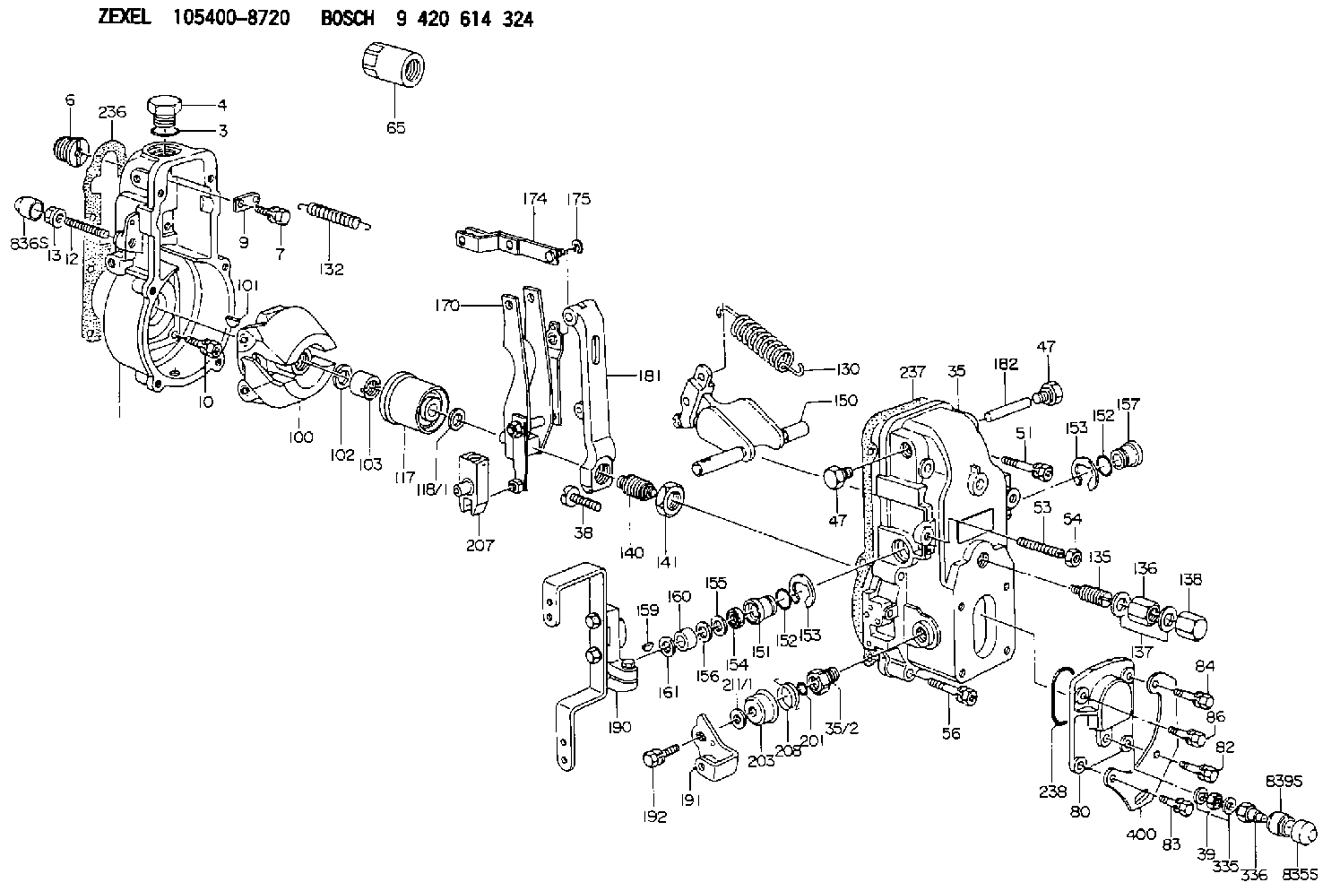
| 1. | [1] | 154000-6300 | GOVERNOR HOUSING |
| 3. | [1] | 029632-5070 | O-RING |
| 4. | [1] | 154007-2900 | CAPSULE |
| 6. | [1] | 154007-0200 | ADAPTOR |
| 7. | [1] | 020018-1840 | BLEEDER SCREW M8P1.25L18 |
| 9. | [1] | 154350-1900 | PLATE |
| 10. | [6] | 029010-6810 | BLEEDER SCREW |
| 12. | [1] | 154013-4000 | FLAT-HEAD SCREW |
| 13. | [1] | 154011-0100 | HEXAGON NUT |
| 35. | [1] | 154500-1020 | GOVERNOR COVER |
| 35/2. | [1] | 154321-0400 | BUSHING |
| 38. | [1] | 154031-2400 | FLAT-HEAD SCREW |
| 39. | [1] | 139206-0600 | UNION NUT |
| 47. | [2] | 154036-0300 | CAPSULE |
| 47. | [2] | 154036-0300 | CAPSULE |
| 51. | [2] | 020106-5040 | BLEEDER SCREW |
| 53. | [1] | 154010-0200 | FLAT-HEAD SCREW |
| 54. | [1] | 154011-4900 | UNION NUT |
| 56. | [4] | 020106-3840 | BLEEDER SCREW |
| 65. | [1] | 155404-5700 | CAP |
| 80. | [1] | 154063-1400 | COVER |
| 82. | [1] | 020006-2040 | BLEEDER SCREW M6P1L20 4T |
| 83. | [1] | 020006-2040 | BLEEDER SCREW M6P1L20 4T |
| 84. | [1] | 020006-2040 | BLEEDER SCREW M6P1L20 4T |
| 86. | [1] | 020006-1640 | BLEEDER SCREW M6P1L16 4T |
| 100. | [1] | 154101-0020 | FLYWEIGHT ASSEMBLY |
| 101. | [1] | 025803-1610 | WOODRUFF KEY |
| 102. | [1] | 029321-2020 | LOCKING WASHER |
| 103. | [1] | 029231-2030 | UNION NUT |
| 117. | [1] | 154123-2320 | SLIDING PIECE |
| 118/1. | [0] | 029311-0010 | SHIM D14&10.1T0.2 |
| 118/1. | [0] | 029311-0180 | SHIM D14&10.1T0.3 |
| 118/1. | [0] | 029311-0190 | SHIM D14&10.1T0.40 |
| 118/1. | [0] | 029311-0210 | SHIM D14&10.1T1 |
| 118/1. | [0] | 139410-0000 | SHIM D14.0&10.1T0.5 |
| 118/1. | [0] | 139410-0100 | SHIM D14.0&10.1T1.5 |
| 118/1. | [0] | 139410-3000 | SHIM D14&10.1T2.0 |
| 118/1. | [0] | 139410-3100 | SHIM D14&10.1T3.0 |
| 118/1. | [0] | 139410-3200 | SHIM D14&10.1T4.0 |
| 130. | [1] | 154150-4100 | GOVERNOR SPRING |
| 132. | [1] | 154154-0800 | COILED SPRING |
| 135. | [1] | 154158-1020 | HEADLESS SCREW |
| 136. | [1] | 154011-1700 | UNION NUT |
| 137. | [2] | 026512-1540 | GASKET D15.4&12.2T1.50 |
| 138. | [1] | 154159-1200 | CAP NUT |
| 140. | [1] | 154178-9220 | HEADLESS SCREW |
| 141. | [1] | 029201-6010 | UNION NUT |
| 150. | [1] | 154200-7120 | SWIVELLING LEVER |
| 151. | [1] | 154204-3000 | BUSHING |
| 152. | [2] | 029631-8020 | O-RING |
| 152. | [2] | 029631-8020 | O-RING |
| 153. | [2] | 016010-1640 | LOCKING WASHER |
| 153. | [2] | 016010-1640 | LOCKING WASHER |
| 154. | [1] | 139611-0000 | PACKING RING |
| 155. | [1] | 139411-0000 | SHIM |
| 156. | [0] | 029311-1070 | SHIM D16&11T0.5 |
| 157. | [1] | 154204-3100 | BUSHING |
| 159. | [1] | 025803-1310 | WOODRUFF KEY |
| 160. | [1] | 154206-2800 | BUSHING |
| 161. | [0] | 154206-0200 | PLAIN WASHER D19.5&11.2T1.0 |
| 170. | [1] | 154210-7320 | FORK LEVER |
| 174. | [1] | 154230-3920 | STRAP |
| 175. | [1] | 016010-0540 | LOCKING WASHER |
| 181. | [1] | 154236-1500 | TENSIONING LEVER |
| 182. | [1] | 154237-0100 | BEARING PIN |
| 190. | [1] | 154343-4920 | CONTROL LEVER |
| 191. | [1] | 154367-1900 | CONTROL LEVER |
| 192. | [1] | 020006-1640 | BLEEDER SCREW M6P1L16 4T |
| 201. | [1] | 029631-0030 | O-RING &9.8W2.3 |
| 203. | [1] | 154322-0100 | CAP |
| 207. | [1] | 154326-5020 | CONTROL LEVER |
| 208. | [1] | 154327-7600 | COILED SPRING |
| 211/1. | [0] | 029311-0520 | SHIM D20.8&10.3T0.2 |
| 211/1. | [0] | 029311-0530 | SHIM D20.8&10.3T0.25 |
| 211/1. | [0] | 029311-0540 | SHIM D20.8&10.3T0.3 |
| 211/1. | [0] | 029311-0550 | SHIM D20.8&10.3T0.35 |
| 211/1. | [0] | 029311-0560 | SHIM D20.8&10.3T0.4 |
| 211/1. | [0] | 029311-0570 | SHIM D20.8&10.3T0.5 |
| 236. | [1] | 154390-0000 | GASKET |
| 237. | [1] | 154390-0300 | GASKET |
| 238. | [1] | 029635-2020 | O-RING |
| 335. | [2] | 026506-1040 | GASKET D9.9&6.2T1 |
| 336. | [1] | 154035-2800 | CAP NUT |
| 400. | [1] | 154358-7200 | BRACKET |
| 835S. | [1] | 154062-4020 | CAP |
| 836S. | [1] | 154062-3520 | CAP |
| 839S. | [1] | 154062-3800 | ADAPTOR |
Include in #1:
101492-0900
as GOVERNOR
Cross reference number
Zexel num
Bosch num
Firm num
Name
105400-8720
8971939310 ISUZU
GOVERNOR
K 14JB MECHANICAL GOVERNOR GOV RSV GOV
K 14JB MECHANICAL GOVERNOR GOV RSV GOV
Information:
Electric Starting
Startability will be improved at temperatures below 16°C (60°F) by the use of a starting aid. A jacket water (coolant) heater or other means can be used to heat the crankcase oil.Start the engine using the following procedure:1. Perform all before-starting inspections.2. If the engine is equipped with a manual control, ensure that is in the RUN position. Place the transmission in NEUTRAL (and disengage the flywheel clutch, if equipped). For Generator Sets, open the main electrical circuit breaker.2. Move throttle to approximately half engine speed to get the fuel rack to move to the FUEL ON position.3. Turn the starter switch to START (or battery disconnect switch to the ON position) or the Engine Control Switch (ECS) to MAN. START. The starting motor will crank and attempt to start the engine. At temperatures below 0°C (32°F), it may be necessary to spray starting fluid into the air cleaner inlet. Additional injections of ether may be required to start and/or achieve low idle speed.
Excessive ether can cause piston and ring damage. When using starting fluid, follow the manufacturer's instructions carefully, use it sparingly and spray it ONLY WHILE CRANKING THE ENGINE. Failure to do so could result in an explosion and/or fire and possible personal injury.Use ether for cold starting purposes only.
Do not crank the engine for more than 30 seconds.
If a warm engine fails to start within 30 seconds: release the starter switch and wait two minutes to allow the starter motor to cool before using it again.4. As soon as the engine starts, allow the engine to idle for 3 to 5 minutes, or until the water temperature gauge indicator has begun to rise. The engine should run at low idle smoothly until speed is gradually increased to high idle.
Do not increase engine speed until the oil pressure gauge indicates normal. Oil pressure should rise within 15 seconds after the engine starts. If oil pressure is not indicated on gauge within 15 seconds, stop the engine, investigate and correct the cause.
5. Allow white smoke to clear up and proceed with normal operation. Do not apply load to the engine or increase engine speed until the oil pressure gauge indicates normal. Oil pressure should raise within 15 seconds after the engine starts. For starting in cold weather, to minimize white smoke: start the engine and allow the engine to idle for 30 seconds. Increase rpm until engine speed reaches 1200 rpm. Then allow the engine to return to low idle.6. Operate the engine at low load until all systems reach operating temperature. Check all gauges during the warm-up period.Engine Starting With Jumper Cables
When boost starting an engine, follow the instructions to properly start the engine. This engine is equipped with a 12 or 24 volt starting system. Use only equal voltage for boost starting. The use of higher voltage will damage the electrical system.
Batteries give off flammable fumes that can explode.Improper jumper cable connections can cause an explosion resulting in personal injury.Prevent sparks near the batteries.