Information governor
BOSCH
9 420 612 427
9420612427
ZEXEL
105400-8061
1054008061
Rating:
Scheme ###:
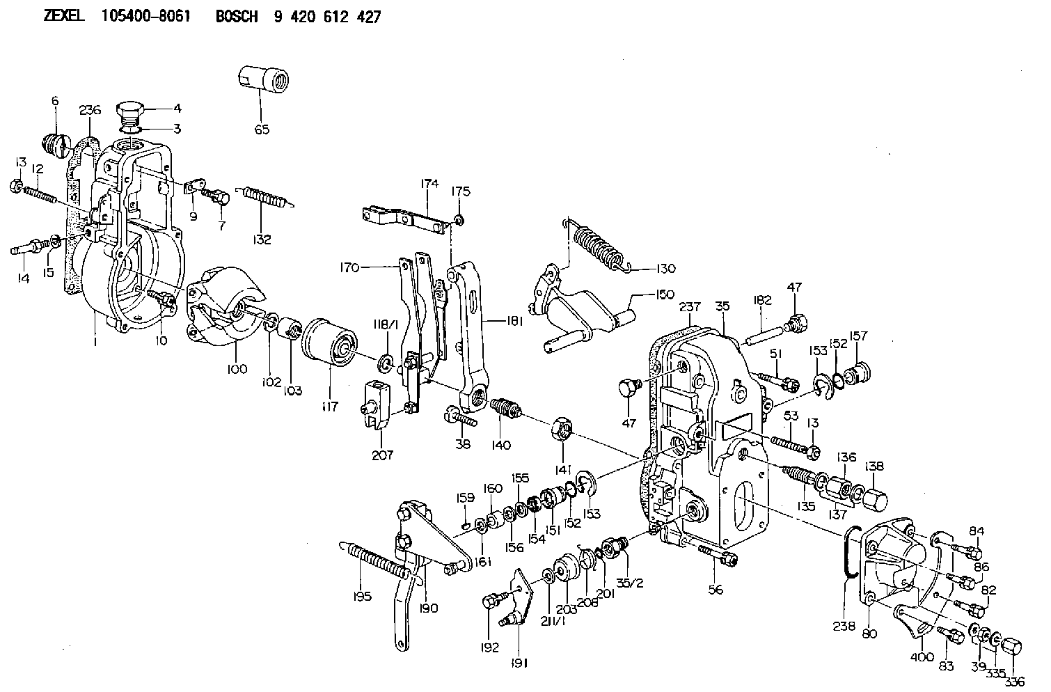
| 1. | [1] | 154000-6300 | GOVERNOR HOUSING |
| 3. | [1] | 029632-5070 | O-RING |
| 4. | [1] | 154007-2900 | CAPSULE |
| 6. | [1] | 154007-0200 | ADAPTOR |
| 7. | [1] | 020018-1840 | BLEEDER SCREW M8P1.25L18 |
| 9. | [1] | 154350-1900 | PLATE |
| 10. | [6] | 029010-6810 | BLEEDER SCREW |
| 12. | [1] | 154010-0100 | FLAT-HEAD SCREW |
| 13. | [2] | 154011-0100 | HEXAGON NUT |
| 13. | [2] | 154011-0100 | HEXAGON NUT |
| 14. | [1] | 154012-2220 | BLEEDER SCREW |
| 15. | [1] | 014110-8440 | LOCKING WASHER |
| 35. | [1] | 154500-1020 | GOVERNOR COVER |
| 35/2. | [1] | 154321-0400 | BUSHING |
| 38. | [1] | 154031-3000 | FLAT-HEAD SCREW |
| 39. | [1] | 139206-0600 | UNION NUT |
| 47. | [2] | 154036-0300 | CAPSULE |
| 47. | [2] | 154036-0300 | CAPSULE |
| 51. | [2] | 020106-5040 | BLEEDER SCREW |
| 53. | [1] | 154010-0100 | FLAT-HEAD SCREW |
| 56. | [4] | 020106-3840 | BLEEDER SCREW |
| 65. | [1] | 154050-1720 | STOPPING DEVICE |
| 80. | [1] | 154063-5100 | COVER |
| 82. | [1] | 029020-6260 | BLEEDER SCREW |
| 83. | [1] | 029020-6260 | BLEEDER SCREW |
| 84. | [1] | 020006-2040 | BLEEDER SCREW M6P1L20 4T |
| 86. | [1] | 020006-1640 | BLEEDER SCREW M6P1L16 4T |
| 100. | [1] | 154101-0120 | FLYWEIGHT |
| 102. | [1] | 029321-2020 | LOCKING WASHER |
| 103. | [1] | 029231-2030 | UNION NUT |
| 117. | [1] | 154123-0120 | SLIDING PIECE |
| 118/1. | [0] | 029311-0010 | SHIM D14&10.1T0.2 |
| 118/1. | [0] | 029311-0180 | SHIM D14&10.1T0.3 |
| 118/1. | [0] | 029311-0190 | SHIM D14&10.1T0.40 |
| 118/1. | [0] | 029311-0210 | SHIM D14&10.1T1 |
| 118/1. | [0] | 139410-0000 | SHIM D14.0&10.1T0.5 |
| 118/1. | [0] | 139410-0100 | SHIM D14.0&10.1T1.5 |
| 118/1. | [0] | 139410-3000 | SHIM D14&10.1T2.0 |
| 118/1. | [0] | 139410-3100 | SHIM D14&10.1T3.0 |
| 118/1. | [0] | 139410-3200 | SHIM D14&10.1T4.0 |
| 130. | [1] | 154150-2700 | GOVERNOR SPRING |
| 132. | [1] | 154154-1200 | COILED SPRING |
| 135. | [1] | 154158-0820 | HEADLESS SCREW |
| 136. | [1] | 154011-1700 | UNION NUT |
| 137. | [2] | 026512-1540 | GASKET D15.4&12.2T1.50 |
| 138. | [1] | 154159-1200 | CAP NUT |
| 140. | [1] | 154177-2120 | HEADLESS SCREW |
| 141. | [1] | 029201-6010 | UNION NUT |
| 150. | [1] | 154200-7120 | SWIVELLING LEVER |
| 151. | [1] | 154204-3000 | BUSHING |
| 152. | [2] | 029631-8020 | O-RING |
| 152. | [2] | 029631-8020 | O-RING |
| 153. | [2] | 016010-1640 | LOCKING WASHER |
| 153. | [2] | 016010-1640 | LOCKING WASHER |
| 154. | [1] | 139611-0000 | PACKING RING |
| 155. | [1] | 139411-0000 | SHIM |
| 156. | [0] | 029311-1070 | SHIM D16&11T0.5 |
| 157. | [1] | 154204-3100 | BUSHING |
| 159. | [1] | 025803-1310 | WOODRUFF KEY |
| 160. | [1] | 154206-2800 | BUSHING |
| 161. | [0] | 154206-0200 | PLAIN WASHER D19.5&11.2T1.0 |
| 170. | [1] | 154210-0920 | FORK LEVER |
| 174. | [1] | 154230-3920 | STRAP |
| 175. | [1] | 016010-0540 | LOCKING WASHER |
| 181. | [1] | 154236-1500 | TENSIONING LEVER |
| 182. | [1] | 154237-0100 | BEARING PIN |
| 190. | [1] | 154395-0020 | CONTROL LEVER |
| 191. | [1] | 154366-8120 | CONTROL LEVER |
| 192. | [1] | 020006-1640 | BLEEDER SCREW M6P1L16 4T |
| 195. | [1] | 154317-0300 | COILED SPRING |
| 201. | [1] | 029631-0030 | O-RING &9.8W2.3 |
| 203. | [1] | 154322-0100 | CAP |
| 207. | [1] | 154326-5020 | CONTROL LEVER |
| 208. | [1] | 154327-7600 | COILED SPRING |
| 211/1. | [0] | 029311-0520 | SHIM D20.8&10.3T0.2 |
| 211/1. | [0] | 029311-0530 | SHIM D20.8&10.3T0.25 |
| 211/1. | [0] | 029311-0540 | SHIM D20.8&10.3T0.3 |
| 211/1. | [0] | 029311-0550 | SHIM D20.8&10.3T0.35 |
| 211/1. | [0] | 029311-0560 | SHIM D20.8&10.3T0.4 |
| 211/1. | [0] | 029311-0570 | SHIM D20.8&10.3T0.5 |
| 236. | [1] | 154390-0000 | GASKET |
| 237. | [1] | 154390-0300 | GASKET |
| 238. | [1] | 029635-2020 | O-RING |
| 335. | [2] | 026506-1040 | GASKET D9.9&6.2T1 |
| 336. | [1] | 154035-1600 | CAP NUT |
| 400. | [1] | 154358-7200 | BRACKET |
Include in #1:
101695-3801
as GOVERNOR
Cross reference number
Zexel num
Bosch num
Firm num
Name
Information:
Your truck may not have the same or all of the gauges as shown in the illustrations. The illustrations shown are of typical gauges.Gauges provide a "look" inside the engine. Be sure they are in good working order. You can determine what is the "normal" operating range by observing your gauges over a period of time.Noticeable changes in gauge readings are indicative of potential gauge or engine problems. This also applies to gauge readings that have changed significantly but are still within specifications. The cause of any sudden or significant change in the readings should be determined and corrected. Contact your Caterpillar dealer for assistance as needed. Oil Pressure - Indicates engine oil pressure. The oil pressure should be between 40 and 88 psi (275 and 606 kPa) when the engine is running at rated engine speed, with SAE 15W-40 oil, at operating temperature. A lower pressure is normal at low idling speed.
If no oil pressure is indicated, stop the engine. Engine damage can result.
Water Temperature - Indicates engine coolant temperture. It should normally indicate between 170°F (77°C) and 208°F (98°C). Somewhat higher temperature may occur under certain conditions. Maximum allowable temperature is 210°F (99°C) with the cooling system pressurized. Ammeter - Indicates the amount of charge or discharge in the battery charging circuit. Normal operation of the indicator should be slightly to the positive (right) side of "0" (zero).With the engine running, during normal operation, if the indicator is constantly to the negative (left) side of "0" (zero) or shows excessive charge, have the charging system checked for malfunction. Tachometer - Indicates engine rpm (speed). The engine can be operated at high idle without damage, but should not be allowed to overspeed. Overspeeding when downshifting, goin downhill, etc., can result in serious damage to your engine.
Do not exceed maximum braking rpm in any situation.
Fuel Level - Indicates fuel level in the fuel tank. Electrically operated, it registers only when the key switch is ON. Fuel Pressure - Indicates fuel pressure to the injection pump. The indicator should register in the NORMAL (green) range.If the indicator moves to the OUT position or registers below 23 psi (160 kPa) when equipped with a numerical gauge, the engine will not operate properly. In most cases this is caused by a plugged fuel filter. Service Hour Meter - Indicates the total number of clock hours the engine has operated.