Information governor
BOSCH
9 420 612 414
9420612414
ZEXEL
105400-7730
1054007730
Rating:
Scheme ###:
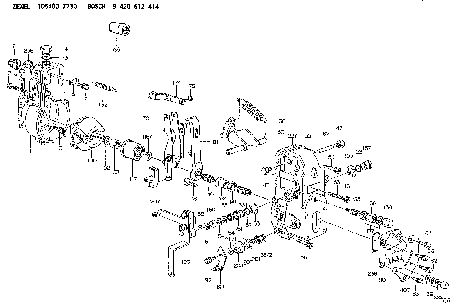
| 1. | [1] | 154000-6300 | GOVERNOR HOUSING |
| 3. | [1] | 029632-5070 | O-RING |
| 4. | [1] | 154007-2900 | CAPSULE |
| 6. | [1] | 154007-0200 | ADAPTOR |
| 7. | [1] | 020018-1840 | BLEEDER SCREW M8P1.25L18 |
| 9. | [1] | 154350-1900 | PLATE |
| 10. | [6] | 029010-6810 | BLEEDER SCREW |
| 12. | [1] | 154010-0100 | FLAT-HEAD SCREW |
| 13. | [2] | 154011-0100 | HEXAGON NUT |
| 13. | [2] | 154011-0100 | HEXAGON NUT |
| 35. | [1] | 154500-1020 | GOVERNOR COVER |
| 35/2. | [1] | 154321-0400 | BUSHING |
| 38. | [1] | 154031-3000 | FLAT-HEAD SCREW |
| 39. | [1] | 139206-0600 | UNION NUT |
| 47. | [2] | 154036-0300 | CAPSULE |
| 47. | [2] | 154036-0300 | CAPSULE |
| 51. | [2] | 020106-5040 | BLEEDER SCREW |
| 53. | [1] | 154010-0100 | FLAT-HEAD SCREW |
| 56. | [4] | 020106-3840 | BLEEDER SCREW |
| 65. | [1] | 154050-1720 | STOPPING DEVICE |
| 80. | [1] | 154063-5100 | COVER |
| 82. | [1] | 029020-6260 | BLEEDER SCREW |
| 83. | [1] | 029020-6260 | BLEEDER SCREW |
| 84. | [1] | 020006-2040 | BLEEDER SCREW M6P1L20 4T |
| 86. | [1] | 020006-1640 | BLEEDER SCREW M6P1L16 4T |
| 100. | [1] | 154101-0120 | FLYWEIGHT |
| 102. | [1] | 029321-2020 | LOCKING WASHER |
| 103. | [1] | 029231-2030 | UNION NUT |
| 117. | [1] | 154123-0120 | SLIDING PIECE |
| 118/1. | [0] | 029311-0010 | SHIM D14&10.1T0.2 |
| 118/1. | [0] | 029311-0180 | SHIM D14&10.1T0.3 |
| 118/1. | [0] | 029311-0190 | SHIM D14&10.1T0.40 |
| 118/1. | [0] | 029311-0210 | SHIM D14&10.1T1 |
| 118/1. | [0] | 139410-0000 | SHIM D14.0&10.1T0.5 |
| 118/1. | [0] | 139410-0100 | SHIM D14.0&10.1T1.5 |
| 118/1. | [0] | 139410-3000 | SHIM D14&10.1T2.0 |
| 118/1. | [0] | 139410-3100 | SHIM D14&10.1T3.0 |
| 118/1. | [0] | 139410-3200 | SHIM D14&10.1T4.0 |
| 130. | [1] | 154150-2700 | GOVERNOR SPRING |
| 132. | [1] | 154154-0701 | COILED SPRING |
| 135. | [1] | 154158-0820 | HEADLESS SCREW |
| 136. | [1] | 154011-1700 | UNION NUT |
| 137. | [2] | 026512-1540 | GASKET D15.4&12.2T1.50 |
| 138. | [1] | 154159-1200 | CAP NUT |
| 140. | [1] | 154178-5420 | HEADLESS SCREW |
| 141. | [1] | 029201-6080 | UNION NUT |
| 150. | [1] | 154200-7120 | SWIVELLING LEVER |
| 151. | [1] | 154204-3000 | BUSHING |
| 152. | [2] | 029631-8020 | O-RING |
| 152. | [2] | 029631-8020 | O-RING |
| 153. | [2] | 016010-1640 | LOCKING WASHER |
| 153. | [2] | 016010-1640 | LOCKING WASHER |
| 154. | [1] | 139611-0000 | PACKING RING |
| 155. | [1] | 139411-0000 | SHIM |
| 156. | [0] | 029311-1070 | SHIM D16&11T0.5 |
| 157. | [1] | 154204-3100 | BUSHING |
| 159. | [1] | 025803-1310 | WOODRUFF KEY |
| 160. | [1] | 154206-2800 | BUSHING |
| 161. | [0] | 154206-0200 | PLAIN WASHER D19.5&11.2T1.0 |
| 170. | [1] | 154210-0920 | FORK LEVER |
| 174. | [1] | 154230-3920 | STRAP |
| 175. | [1] | 016010-0540 | LOCKING WASHER |
| 181. | [1] | 154236-1500 | TENSIONING LEVER |
| 182. | [1] | 154237-0100 | BEARING PIN |
| 190. | [1] | 154343-5020 | CONTROL LEVER |
| 191. | [1] | 154366-8120 | CONTROL LEVER |
| 192. | [1] | 020006-1640 | BLEEDER SCREW M6P1L16 4T |
| 201. | [1] | 029631-0030 | O-RING &9.8W2.3 |
| 203. | [1] | 154322-0100 | CAP |
| 207. | [1] | 154326-5020 | CONTROL LEVER |
| 208. | [1] | 154327-7600 | COILED SPRING |
| 211/1. | [0] | 029311-0520 | SHIM D20.8&10.3T0.2 |
| 211/1. | [0] | 029311-0530 | SHIM D20.8&10.3T0.25 |
| 211/1. | [0] | 029311-0540 | SHIM D20.8&10.3T0.3 |
| 211/1. | [0] | 029311-0550 | SHIM D20.8&10.3T0.35 |
| 211/1. | [0] | 029311-0560 | SHIM D20.8&10.3T0.4 |
| 211/1. | [0] | 029311-0570 | SHIM D20.8&10.3T0.5 |
| 236. | [1] | 154390-0000 | GASKET |
| 237. | [1] | 154390-0300 | GASKET |
| 238. | [1] | 029635-2020 | O-RING |
| 331. | [1] | 154172-9320 | HEADLESS SCREW |
| 332. | [1] | 029201-6010 | UNION NUT |
| 335. | [2] | 026506-1040 | GASKET D9.9&6.2T1 |
| 336. | [1] | 154035-1600 | CAP NUT |
| 400. | [1] | 154358-7200 | BRACKET |
Include in #1:
101695-3650
as GOVERNOR
Cross reference number
Zexel num
Bosch num
Firm num
Name
Information:
Crankcase Breather
Clean
1. Loosen hose clamp (1) and remove the hose from the cover.2. Loosen three breather cover bolts (2) and remove cover (3). 3. Remove breather element (4), and wash in clean, nonflammable solvent and allow to dry. 4. Install clean, dry breather element (4).5. Install cover (3) and bolts (2).5. Install hose and clamp (1). Tighten clamp (1), refer to topic "Torque Specifications" for the proper torque of hose clamp-worm drive band type. If the crankcase breather is not maintained on a regular basis, it will become plugged. A plugged crankcase breather would result in excessive crankcase pressure that may cause crankshaft seal leakage.Alternator, Fan and Accessory Drive Belts
Inspect/Replace
Inspect the condition and adjustment of alternator belts and fan drive belts.Inspect the drive belts for wear and replace if they show any signs of wear. If one belt in a set requires replacement, always install a new matched set of belts. Never replace just the worn belt. If only the worn belt is replaced, the new belt will carry all the load, as it will not be stretched as much as the older belts. All the belts will fail in rapid succession.Belt Adjustment
* To check the belt tension, apply 25 lbs (110 N) of force midway between the pulleys. Correctly adjusted belts will deflect 1/2 to 3/4 inch (13 to 19 mm).If belts are too loose, they vibrate enough to cause unnecessary wear on the belts and pulleys. If belts are too tight, unnecessary stresses are placed upon the pulley bearings and belts which might shorten the life of both.The engine is equipped with an automatic belt tensioner, adjustments should not be necessary.Hoses and Clamps
Inspect/Replace
Hose replacement prior to failure is a cost effective preventive maintenance practice. Replacing a hose before it fails saves money and reduces the chances for unscheduled downtime. By replacing a hose that is cracked, soft or leaking, you will avoid major repairs that could result in a severe engine overheating problem. * Inspect all hoses for leaks due to cracking, softness and loose clamps.* Replace hoses that are cracked or soft and tighten loose clamps.Before Replacing Hoses
1. After engine is cool, loosen the radiator filler cap slowly to relieve any pressure and remove the cap.2. Drain the coolant from the cooling system to a level below the hose being replaced.3. Remove the hose clamps, disconnect the old hose and replace with a new hose.4. Install hose clamps. (See the Torque for Standard Hose Clamps-Worm Band Type chart in the Torque Specifications section of this publication for the appropriate torque.) For constant torque hose clamps, see the Torque Specifications section in this publication.After Replacing Hoses
Refer to the Cooling System Specifications and Cooling System-Test for Coolant Additive maintenance topics in this publication.5. Add coolant mixture to the cooling system. Bring it to the proper level by mixing a solution of acceptable water and Caterpillar Antifreeze. Test for supplemental additive (Conditioner) concentration. Add proper amount, or if equipped with a coolant additive element, install the appropriate element