Information governor
BOSCH
9 420 612 413
9420612413
ZEXEL
105400-7720
1054007720
Rating:
Scheme ###:
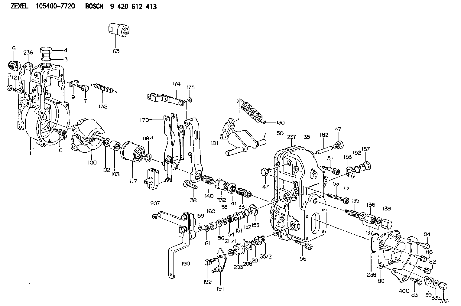
| 1. | [1] | 154000-6300 | GOVERNOR HOUSING |
| 3. | [1] | 029632-5070 | O-RING |
| 4. | [1] | 154007-2900 | CAPSULE |
| 6. | [1] | 154007-0200 | ADAPTOR |
| 7. | [1] | 020018-1840 | BLEEDER SCREW M8P1.25L18 |
| 9. | [1] | 154350-1900 | PLATE |
| 10. | [6] | 029010-6810 | BLEEDER SCREW |
| 12. | [1] | 154010-0100 | FLAT-HEAD SCREW |
| 13. | [2] | 154011-0100 | HEXAGON NUT |
| 13. | [2] | 154011-0100 | HEXAGON NUT |
| 35. | [1] | 154500-1020 | GOVERNOR COVER |
| 35/2. | [1] | 154321-0400 | BUSHING |
| 38. | [1] | 154031-3000 | FLAT-HEAD SCREW |
| 39. | [1] | 139206-0600 | UNION NUT |
| 47. | [2] | 154036-0300 | CAPSULE |
| 47. | [2] | 154036-0300 | CAPSULE |
| 51. | [2] | 020106-5040 | BLEEDER SCREW |
| 53. | [1] | 154010-1100 | FLAT-HEAD SCREW |
| 56. | [4] | 020106-3840 | BLEEDER SCREW |
| 65. | [1] | 154050-1720 | STOPPING DEVICE |
| 80. | [1] | 154063-5100 | COVER |
| 82. | [1] | 029020-6260 | BLEEDER SCREW |
| 83. | [1] | 029020-6260 | BLEEDER SCREW |
| 84. | [1] | 020006-2040 | BLEEDER SCREW M6P1L20 4T |
| 86. | [1] | 020006-1640 | BLEEDER SCREW M6P1L16 4T |
| 100. | [1] | 154101-0120 | FLYWEIGHT |
| 102. | [1] | 029321-2020 | LOCKING WASHER |
| 103. | [1] | 029231-2030 | UNION NUT |
| 117. | [1] | 154123-0120 | SLIDING PIECE |
| 118/1. | [0] | 029311-0010 | SHIM D14&10.1T0.2 |
| 118/1. | [0] | 029311-0180 | SHIM D14&10.1T0.3 |
| 118/1. | [0] | 029311-0190 | SHIM D14&10.1T0.40 |
| 118/1. | [0] | 029311-0210 | SHIM D14&10.1T1 |
| 118/1. | [0] | 139410-0000 | SHIM D14.0&10.1T0.5 |
| 118/1. | [0] | 139410-0100 | SHIM D14.0&10.1T1.5 |
| 118/1. | [0] | 139410-3000 | SHIM D14&10.1T2.0 |
| 118/1. | [0] | 139410-3100 | SHIM D14&10.1T3.0 |
| 118/1. | [0] | 139410-3200 | SHIM D14&10.1T4.0 |
| 130. | [1] | 154150-2700 | GOVERNOR SPRING |
| 132. | [1] | 154154-0701 | COILED SPRING |
| 135. | [1] | 154158-0820 | HEADLESS SCREW |
| 136. | [1] | 154011-1700 | UNION NUT |
| 137. | [2] | 026512-1540 | GASKET D15.4&12.2T1.50 |
| 138. | [1] | 154159-1200 | CAP NUT |
| 140. | [1] | 154178-5420 | HEADLESS SCREW |
| 141. | [1] | 029201-6080 | UNION NUT |
| 150. | [1] | 154200-7120 | SWIVELLING LEVER |
| 151. | [1] | 154204-3000 | BUSHING |
| 152. | [2] | 029631-8020 | O-RING |
| 152. | [2] | 029631-8020 | O-RING |
| 153. | [2] | 016010-1640 | LOCKING WASHER |
| 153. | [2] | 016010-1640 | LOCKING WASHER |
| 154. | [1] | 139611-0000 | PACKING RING |
| 155. | [1] | 139411-0000 | SHIM |
| 156. | [0] | 029311-1070 | SHIM D16&11T0.5 |
| 157. | [1] | 154204-3100 | BUSHING |
| 159. | [1] | 025803-1310 | WOODRUFF KEY |
| 160. | [1] | 154206-2800 | BUSHING |
| 161. | [0] | 154206-0200 | PLAIN WASHER D19.5&11.2T1.0 |
| 170. | [1] | 154210-0920 | FORK LEVER |
| 174. | [1] | 154230-3920 | STRAP |
| 175. | [1] | 016010-0540 | LOCKING WASHER |
| 181. | [1] | 154236-1500 | TENSIONING LEVER |
| 182. | [1] | 154237-0100 | BEARING PIN |
| 190. | [1] | 154343-5020 | CONTROL LEVER |
| 191. | [1] | 154366-8120 | CONTROL LEVER |
| 192. | [1] | 020006-1640 | BLEEDER SCREW M6P1L16 4T |
| 201. | [1] | 029631-0030 | O-RING &9.8W2.3 |
| 203. | [1] | 154322-0100 | CAP |
| 207. | [1] | 154326-5020 | CONTROL LEVER |
| 208. | [1] | 154327-7600 | COILED SPRING |
| 211/1. | [0] | 029311-0520 | SHIM D20.8&10.3T0.2 |
| 211/1. | [0] | 029311-0530 | SHIM D20.8&10.3T0.25 |
| 211/1. | [0] | 029311-0540 | SHIM D20.8&10.3T0.3 |
| 211/1. | [0] | 029311-0550 | SHIM D20.8&10.3T0.35 |
| 211/1. | [0] | 029311-0560 | SHIM D20.8&10.3T0.4 |
| 211/1. | [0] | 029311-0570 | SHIM D20.8&10.3T0.5 |
| 236. | [1] | 154390-0000 | GASKET |
| 237. | [1] | 154390-0300 | GASKET |
| 238. | [1] | 029635-2020 | O-RING |
| 331. | [1] | 154172-9320 | HEADLESS SCREW |
| 332. | [1] | 029201-6010 | UNION NUT |
| 335. | [2] | 026506-1040 | GASKET D9.9&6.2T1 |
| 336. | [1] | 154035-1600 | CAP NUT |
| 400. | [1] | 154358-7200 | BRACKET |
Include in #1:
101695-3640
as GOVERNOR
Cross reference number
Zexel num
Bosch num
Firm num
Name
Information:
* Inspect the radiator for leaks and trash build-up. * Inspect the radiator hoses for cracks and loose clamps. * Inspect the fan and accessory drive belts for cracks, breaks or other damage.Belts for multiple groove pulleys must be replaced as matched sets. If only one belt of a 2 or 3 belt set is replaced, it will carry more of a load than the belts not replaced since the older belts are stretched. The additional load on the new belt could cause it to break. * Inspect the water pump for leaks. * Inspect the engine for oil leaks, such as front and rear crankshaft seals, oil pan, oil filters and valve covers. * Inspect the fuel system for leaks, loose fuel line clamps and fittings and loose or worn hoses. * Inspect wiring for loose connections and worn or frayed wires. * Inspect air intake system hoses and elbows for cracks and loose clamps. * Inspect ECM to cylinder head ground strap for good connection and condition.* Inspect engine-to-frame ground strap for good connection and condition.* All guards must be in place. Repair or replace missing or damaged guards.Engine Crankcase
Check Oil Level
Make sure you read and understand the information in the Lubricant Specifications section of this manual before you proceed with maintenance of the crankcase lube oil system.
The vehicle must be parked on a level surface to perform this maintenance procedure.
1. Check the oil level with the engine stopped. 2. Maintain the oil level between the ADD and FULL marks in the FULL RANGE zone on the ENGINE STOPPED side of the dipstick. Do not fill the crankcase above the FULL RANGE zone. Operating your engine when the oil level is above the FULL RANGE zone could cause your crankshaft to dip into the oil. If this happens, the air bubbles created from the crankshaft dipping into the oil will reduce the lubricating characteristics of your oil and would result in the loss of power.If the dipstick does not have a FULL mark in the FULL RANGE zone, refer to Calibrating the oil level gauge in the Dipstick section of this manual or consult your Caterpillar dealer before changing oil and operating the engine. 3. Remove the oil filler cap and add oil if necessary. See Refill Capacities and Lubricant Specifications for the size of your engine crankcase and proper oil to use. Remote mounted or auxiliary filters require additional oil. For all information pertaining to auxiliary filters, refer to the OEM or filter manufacturer's instructions.Cooling System
Check Coolant Level
Make sure you read and understand the information in the "Cooling System Specifications" section of this manual before you proceed with maintenance of the cooling system.
1. Check the coolant level with the engine stopped and cool.2. Remove the filler cap slowly to relieve any pressure.3. Maintain the coolant level within 13 mm (1/2 inch) below the bottom of the fill pipe or to the proper level on the sight glass, if equipped. 4. Inspect the filler cap.Replace the